Quantcast
Channel: Firearms History, Technology & Development
Viewing all 263 articles
Browse latest View live

Videos: Button Rifling

$
0
0
In our last post, we looked at a video showing broach rifling in action, a subject we had studied many months ago. In today's post, we will revisit the process of button rifling. We had studied this process many months ago, here on this forum. In order to refresh your memory, here's a link to that original post describing the process of button rifling.

Now that you've read about the process, let's look at a movie displaying the process in action:


The movie above shows the process of button rifling a barrel, using a button that is pulled through the barrel. Notice how the chuck on the left rotates the barrel, as the button is being pushed through.

In the original article about button rifling that we linked above, we mentioned that there are two different ways for the button to be used. The button can be either pulled through the barrel (like the video above shows), or it can be pushed through the barrel, as the following video shows:


Note that in the second video, the barrel is not rotated as the button is pushed through. Instead, the button rotates as it is being pushed through the barrel.

Happy viewing!


Videos: Hammer Forged Rifling

$
0
0
In our last post, we looked at a couple of videos showing how button rifling works. This is a technique we had studied many months ago. In today's post, we will revisit another technique that we had studied back in May 2010, hammer forged rifling. To refresh your memory, here's a link to the original post, describing the process of hammer forged rifling.

Now that you've read that post, let us watch a couple of videos showing the process in action. First up, we have a short video from Daniel Defense, a well known manufacturer of firearms and firearm parts here in America. While many American manufacturers prefer to use button rifling to make their barrels, Daniel Defense uses hammer forging machines.


As we mentioned in the original post, hammer forged rifling is much more prevalent in Europe than America. Here's a couple more videos of the process, from European manufacturers. The next video is from Armalon UK:


And finally, we have another video about the process, as done by the Steyr Mannlicher factory in the town of Steyr, Austria. Incidentally, the leading manufacturer of hammer forging machines in the world is an Austrian company called GFM GmbH, which is also located in the town of Steyr! It is interesting to note that Steyr Mannlicher actually uses a slightly different process to make their barrels, than most other manufacturers of hammer forged barrels. The following video describes their process and also how they do some things differently than other companies.


Happy viewing!

Videos: Flow Forming

$
0
0
In our last post, we looked at a few videos showing how hammer forging works. In today's post, we will revisit another technique to manufacture rifling that we studied several months ago: flow forming. To refresh your memory, here's a link to that original post describing flow forming.

This is a relatively new technique and therefore there don't appear to be any videos on youtube specifically showing this process being used to make gun barrels. However, there are videos showing how a flow forming machine is used to form tubes, which is close enough for our purposes to understand the principles behind this method.


Happy viewing.

Ancient Techniques of Rifling Machines - I

$
0
0
In the last few posts, we studied somevideos of riflingtechniques and we had also studied the descriptions of these techniques in detail many months earlier. The thing to note though is that all these videos showed relatively modern machinery making the rifling. In fact, the oldest machine in those videos dates to some time in the early 1900s. However, as we have seen earlier, the history of rifling dates back to about 1520, well before such automated rifling machines were invented. So how did people historically cut rifling grooves into their barrels, without the aid of modern machinery? We will attempt to reconstruct their techniques in the next series of posts, only using technologies that would have existed in the 1500s and 1600s. As we are studying the techniques, it will become fairly obvious to the reader, that historical gunsmiths would have had some pretty good skills in both woodworking and metalworking, which is why they formed separate gunsmithing guilds, which were different from carpentry and blacksmith guilds.

The first tool that any gunsmith would have used would have been a lathe. This handy tool was known to the ancient Egyptians in 1300 BC and later spread to the Greeks, Indians, Assyrians and Romans. The first design simply had one person pulling a rope to rotate a wooden work piece around two centers and the other person would apply a sharp edged tool to the rotating wooden piece, to cut it into a cylinder or a tapered cylinder or a similar shape.


Two images of lathes, as used in ancient Egypt

The basic two-person operated lathe concept was modified by other cultures, as shown in the example from India below:

Horizontal two person lathe used in Ancient India.

The Romans came up with a lathe design that used a bow to turn the wooden work-piece. With this type of lathe, there is no need for a second person, as a single person can move the bow with one hand and manipulate the cutting tool with the other hand.


The bow lathe design stayed with us for quite a long time: small bow lathes were still used by clockmakers in the early 1800s.

In the middle ages, someone got the idea of tying one end of the rope to a thin springy pole or branch and the other end to a foot pedal and the rope would loop around the wooden work piece to be turned. The craftsman would use his foot to operate the pedal and use his two hands to hold various tools against the turning wood piece.

Spring pole lathes from the middle ages

The above illustrations show some spring pole lathes from the middle ages. The left side illustration is based on a Parisian manuscript from the 13th century. As with bow lathes, spring pole lathes do not need for a second person to turn the wood piece. Spring pole lathe designs were commonly used for hundreds of years, all the way to the early part of the 20th century!

Other lathe designs included using horses, flowing water, steam and electricity to power them and lathes evolved to cut both wood and metal pieces.

Ancient Techniques of Rifling Machines - II

$
0
0
In our last post, we started a series on studying how people used to cut rifling in their barrels manually, without the benefit of modern machinery. In our last post, we left off with the study of an important woodworking and metalworking tool, the lathe. As we saw in our last post, lathes were available to various cultures around the world, since the times of ancient Egypt, so it is pretty reasonable to assume that they were available to people around 1500 AD as well.

In today's post, we will look into the construction of an indexing guide. This is basically the part of the rifling machine that twists the cutting tool at a fixed rate, so that it cuts the required rifling grooves inside the barrel. This is the one part of an ancient rifling machine that needs to be as accurate as possible. Of course, we will first study how they built the most complicated part, so that the rest will appear a lot easier!

As we studied in our previous post, lathes can be used to make cylindrical shapes. The workman simply mounts a log of wood on his lathe and starts turning it and applies a sharp tool to the side of the rotating log to carve out a cylinder. So our ancient gunsmith would have used a lathe to carve a wooden cylinder made of oak or maple, about 4 inches in diameter and at least 50 inches long (assuming that he wants to make a rifled barrel with a twist rate of 1 turn in 48 inches, which is a typical twist rate of that era, so he makes the cylinder at least 48 inches long, with a little bit extra), with smaller protruding cylinders at either end of the log, such as the illustration below shows (please excuse the crudeness of the drawing :)):

Click on image to enlarge. Author places this image in the public domain,

The next thing to do is inscribe a groove on the thickest part of the cylinder (i.e. the part that is 50 inches long). The groove will help guide the cutting tool at the required twist rate.

The groove forms a helical path on the outside of the cylinder. So how did people build this in the middle ages. Luckily for us, there is a simple way to do this, which has been with us since ancient times. First, the gunsmith draws two sides of a right triangle ABC on a flat surface as follows:

Two sides of a right triangle. Clck on image to enlarge

Here, AB is 48 inches long (because we wanted a twist rate of 1 turn in 48 inches) and the length of side BC is equal to the circumference of the wooden log that was just shaped. The gunsmith can calculate the length of BC to be (pi * diameter of the cylinder), or the gunsmith can simply measure this out by wrapping a thin thread around the surface of the cylinder and marking it, then placing the thread on the line BC and measuring out the length of the markings. The only trick is ensuring that the angle ABC is a right angle (i.e. 90 degrees) and as we will see, measuring this out is a piece of cake as well.

Sidebar: How to measure a right angle

This might be a good time to talk about how people measured right angles back in the day, if only for the reason that such knowledge of geometry is gradually being lost today unfortunately. Today, any student can buy a protractor at any stationary shop for a couple of dollars (A 10 piece Staedtler mathematical instrument set cost me $3.99 and it contains a protractor, two set squares, a compass, pencil sharpener, pencil, a ruler etc.). However, a protractor wasn't in common use before the 19th century and such instruments were generally more expensive before the 19th century and weren't easily affordable to ordinary smiths. So let us only consider instruments that were cheap and widely available for that era.

As it turns out, ancient civilizations like the Egyptians and the Chinese had already developed set squares, way back in the day (Egyptians seem to have had them as far back as 1300 BC or so), so they were probably widely available to various people in the middle ages as well. While you can't measure any angle with a set square like you can with a protractor, they can be used to measure right angles very well.

Ancient Egyptian set square from 1300 BC.

The above instrument is from ancient Egypt and such instruments were known back in the time of the Pharoah Ramses and used by them to build pyramids, so they were definitely widely available in many countries by the middle ages. Using one of these instruments, a gunsmith could have easily drawn a right angle.

The other ancient mathematical instrument is the compass, which was also known to ancient civilizations like the Greeks, Chinese, Indians, Romans etc. For example, Euclid's classic mathematical work Elements from around 300 BC mentions compass and straight-edge problems in book II of the series, and a classic Chinese mathematical text, the Zhoubi Suanjing from around 100 BC, also mentions the use of set square and compass in geometry problems. Ancient compass instruments have been found intact in the ruins of Roman cities like Pompeii and ancient Indian mathematical texts also talk about usage of such instruments.

A set of bronze compasses from the Roman era

Even if a person has no compass, he can still improvise with two sharp objects (e.g. two pencils) and a ribbon connecting the two sharp objects together at a given length. As we will see below, we can still draw a fairly accurate right angle with such a crude instrument, using the procedure below:


Say we have a line AB and we wish to draw a right angle at point B. Imagine that the only instruments that the gunsmith has available are a straight edge and a compass (and if he doesn't have a compass, he has improvised by tying two pencils, one on each end of a shoe lace!). The first thing to do is to mark the point B and then use the straight edge to extend the line AB beyond the point B, as shown in the illustration below:

Then, he opens his compass (or his crude shoe-lace and pencil contraption) to any convenient length and using B as the center, he draws two arcs on either side of B to mark out C and D as shown below:

Now, he opens the compass out a bit so that it measures out any arbitrary distance greater than BC (it can be greater than CD also, it doesn't matter). Then using point C as the center, he uses the compass to draw an arc above line AB as shown in the image below:

Then, using the compass set to the same length as the previous step and using D as the center, he draws another arc above line AB, that intersects the previous arc at point E, as shown below:

Now, he uses the straight edge to connect points B and E together in a straight line as shown in the figure below:
 Voila, angle ABE is a right angle and it has been drawn without any sophisticated (for that time) instruments at all.

Now back to topic...

Now that we know how to construct a right angle with simple tools, we go back to our original figure ABC, where line AB is 48 inches long and BC is the diameter of the wooden log that the gunsmith intends to use as an indexing guide. The gunsmith then uses a ribbon or a thread dipped in glue to connect points AC, such as in the figure shown below:

Then, the gunsmith places the indexing cylinder guide so that it is touching AB and rolls it up, so that the sticky thread on AC gets wound on the outside of the cylinder. Instead of using sticky thread, the gunsmith can also mark AC with a dark charcoal marker, so that the marking gets transferred to the indexing cylinder when the cylinder is rolled on it. The procedure is shown below:


Now that the cylinder is marked properly, the gunsmith can use a sharp chisel and mallet to cut a groove along the path marked by the sticky tape. Voila, the groove is produced at the desired twist rate and we have our indexing guide, as shown in the image below:


The indexing guide was actually one of the trickiest parts that the gunsmith needed to manufacture for his manual rifling machine. As you can see, even in the middle ages without access to any sophisticated modern tools, it was possible for a skilled workman to construct an indexing guide pretty accurately.

In the next post, we will look at the next part that needs to be constructed relatively accurately, the indexing head and pin. Then we will look at how the remaining parts were built and how the machine was assembled in subsequent posts.

Ancient Techniques of Rifling Machines - III

$
0
0
In our last post, we saw how a gunsmith from hundreds of years ago, could construct an indexing guide, a key part of a manual rifling machine. In today's post, we will study how they could make the indexing head, another key part of the machine. Like the indexing guide, the indexing head is also constructed as accurately as possible.

The purpose of the indexing head is for the indexing guide to pass through. This is the part that serves to rotate the indexing guide at a precise twist rate, which is in turn, used to move the cutting tool inside the barrel and cut the rifling grooves. Here's what the indexing head looks like:

Click on image to enlarge. Author places the image into the public domain. Some dimensions are not to scale.

The gunsmith starts with a flat plank of wood of suitable size. The gunsmith then bores a large hole B in the plank, to a diameter slightly larger than the indexing guide that we studied in the previous post. In the previous post, we had decided that the indexing guide had a diameter of 4 inches at its thickest part. Therefore, the diameter of the hole B is drilled to about 4.25 inches, so that the indexing guide can fit through this hole with a bit of clearance.

After that, the gunsmith chisels a hole at one edge of the hole B, so that he can screw in a small indexing pin A. The indexing pin A can be made of steel, brass or any hard wood such as oak, maple etc. The material is simply cut from a blank using a hacksaw blade and then filed into shape, and a hole is drilled in the middle to support a screw. The indexing pin is made long enough to fit in the groove that was cut in the indexing guide we saw in the previous post.


Building the indexing pin. Click on image to enlarge.

The indexing pin is inlaid into the indexing head, so that it cannot move at all.

The gunsmith also drills three or four holes C, at the bottom of the indexing head, so that the indexing head can be attached to the rifling machine bed via screws through these holes.

The indexing head mates with the indexing guide from our last post, as shown in the image below:

Click on image to enlarge

The indexing head is fixed to the bed of the rifling machine and the indexing guide is pushed through it. The indexing pin fits into the groove of the indexing guide and causes the guide to rotate at a fixed rate, as it is being pushed or pulled through the head.

Of course, the curious reader might ask, how does a person drill such a large hole like B into a plank of wood. Luckily for us, the tools to do this were already invented and perfected several hundreds of years ago. Remember that mankind has been using the wheel for thousands of years and the wheel is attached to the axle with a relatively large hole. The first solid wheels and axles began to appear in Mesopotamia, Central Europe, Balkans and Northern Caucasus around 3500 BC. By about 3000 BC, the Indus valley civilization in Northern India shows evidence of having spoked wheels. By 1200 BC, chariots with spoke wheels were known to just about everyone in Europe and Asia and parts of Africa as well. Therefore, the technology for boring large holes into objects (e.g. for attaching an axle to a wheel and attaching spokes to wheels) was pretty well developed by this point in time. Tools such as the bow-drill and gimlets could be used to drill smaller holes and then the holes could be enlarged by using augers and reamers.

A Bow Drill

An Auger. Click on image to enlarge.

Several examples of Reamers. In particular, note the one from Roman times. Click on image to enlarge

A wheelwright using boring tools to fit an axle to a wheel. Click on image to enlarge,

While the images above show the tools used by a wheelwright to bore a hole into a wheel for an axle, the same tools and techniques were also used by ship builders, architects, carpenters etc. Therefore, it is a pretty safe bet to say that a gunsmith in 1500 AD had the tools and knowledge to easily bore a large hole into an indexing head.

The parts in this post and the previous one need to be built as accurately as possible, to produce good rifling. In the next few posts, we will study some of the other parts needed to build the manual rifling machine.


Ancient Techniques of Rifling Machines - IV

$
0
0
In our last post, we saw how an ancient gunsmith could have built an indexing head and in the post before that, we saw how they could build an indexing guide. In todays post, we will look into how they would mount the indexing guide and indexing head together, along with the head piece and tail piece.

As we noticed in the post for the indexing guide, the cylinder is mostly about 4" in diameter, except at the ends, where the diameter is 2" or 3" on either end.


The ends are where we will mount the head piece and tail piece. First, we look at the head piece.

The Head Piece. Click on image to enlarge. Not to scale.
Author places the image in the public domain.

It consists of a rectangular board of wood in which a few holes are drilled or chiselled out. Holes A and C are rectangular holes which are identical in dimensions. Hole B is a circular hole which is drilled to the diameter 3" (i.e.) the diameter of the cylinder at the right end of the indexing guide. It must be noted that the distance between the holes A and C must be greater than the width of the indexing head that we studied in the previous post. We will see why shortly. Finally, the gunsmith attaches handles on either side of the head piece.

Next, we look at the tail piece.

The Tail Piece. Click on image to enlarge. Not to scale.
Author places the image in the public domain.

In this piece, there are two notches A and C, which are to identical dimensions of A and C in the head piece above. The distance between A and C is also exactly the same as between A and C in the head piece above. The hole B is drilled to a diameter of 2", or exactly the diameter of the cylinder at the left end of the indexing guide. Finally, we have a large section D, which is the width of the bed of the indexing machine. We will see how this all fits in the next few images.

The gunsmith takes two long pieces of pine wood which are 1 inch x 2 inch in cross-section and about 50 inches long and attaches them to holes A and C on the head piece and tail pieces, using glue and nails. These long pine pieces act as braces and connect the head piece and tail piece together He also slips in the indexing piece into holes B on the head piece and tail piece. The figure below shows how the tail piece attaches to the indexing guide:

Tail piece assembly. Click on image to enlarge. Not to scale.
Author places the image in the public domain.

The next image shows how the head piece, tail piece, indexing head and indexing guide are all attached to the bed. First, the gunsmith selects a long plank of wood as the bed of the machine. Then he attaches the indexing head to one end, using nails or screws to secure it. Then he screws in the indexing pin  to the indexing head and passes the indexing guide through the hole. Then he attaches the head piece and tail piece to either end of the indexing guide and then connects the wooden braces to the head piece and tail piece. Note that the section D on the tail piece is wide enough to slide on top of the bed of the machine. The assembly so far looks something like this:

Assembly of the manual rifling machine. Click on image to enlarge. Not to scale.
Author places the image in the public domain.

The gunsmith can now grab the two handles on either side of the head piece and slide it back and forth along the bed. As the head piece and tail piece slide along the bed, the indexing guide also moves along with them. Due to the groove in the indexing guide meshing with the indexing pin on the indexing head (which is fixed to the bed and does not move), the indexing guide rotates at a fixed rate, equal to the groove's twist rate (which we saw how to machine, two posts earlier).

In the next few posts, we will see how our ancient gunsmith could have fashioned a cutting tool and attached it to the indexing guide and also see how the rest of the machine is built. Happy reading!

Ancient Techniques of Rifling Machines - V

$
0
0
In our last post, we saw how an ancient gunsmith would build the head piece and tail piece and assemble some of the parts of the manual rifling machine. In today's post, we will deal with another important part of the machine, the rifling cutter.

Briefly, the rifling cutter is the part that actually cuts the grooves on the barrel. There were several designs of rifling cutters over the ages and we will study some of the common variants in today's post. First, we have the actual cutting tool. This was usually made of forged steel, with one or more sharp cutting edges. Once the sharp cutting edge was formed, the gunsmith would harden the cutting tool using the same heat treatment techniques that were known to sword smiths.

A cutting tool. Click on image to enlarge. Author places image in public domain. Not to scale.

In the above image, we see a cutting tool with two teeth. A cutting tool could have a single cutting tooth or multiple teeth, depending upon the gunsmith's desires.

This cutting now needs to be mounted to a cutter body, so that it can be used in a rifling machine. The simplest rifling cutters had the bodies made of wood. The gunsmith would first use a lathe to make a wooden cylinder out of a hard wood (such as oak or hickory), a little less than the diameter of the barrel to be rifled. Then the gunsmith would chisel out a slot on the top of the cylinder, just big enough to insert the cutting tool into the slot. The gunsmith would then insert the cutting tool into the slot and add glue to fasten the tool to the cutter body. Finally, as an optional extra precaution, the gunsmith would also wind some wet twine around the cutter body to overlap the tool's body. As the twine dries up, it tightens around the wood and secures the cutter extra-tightly to the body.

A simple rifling cutter. Click on image to enlarge. Author places the image in the public domain. Not to scale.

The above image shows how ancient gunsmiths would construct such a cutter. The advantage of this type of cutter is that it is relatively easy to construct. However, the height of the groove cannot be adjusted easily with this type of cutter. The solution is to adjust the barrel's position to deepen a groove and we will study that when we look at barrel clamps. In other cases, the gunsmith would simply move the cutter back and forth until it cut the groove to the required depth throughout the length of the barrel.

A slightly better modification to the above design was also used by ancient gunsmiths. The gunsmith would construct a wooden cylinder out of oak or hickory, using a lathe. Unlike the previous cutter body though, this one would have a thicker cylinder in the center and two smaller cylinders at the end. Then, the gunsmith would split the cylinder into two pieces lengthwise and then carve out a long groove on each of the halves. The gunsmith would then attach the cutting tool to one of the pieces and then glue the two halves back together and secure the ends with twine or tight leather bands. In the gap between the long grooves, the gunsmith would force two tight fitting wooden shims in, before gluing the two halves together. The image below shows how this was done:

Ancient Rifling Cutter. Click on image to enlarge. Author places the image into the public domain. Not to scale.

In this type of cutter, the gunsmith can move the cutting tool down or up by moving the two shims closer to or away from the center of the cutter. Alternatively, the gunsmith can add more padding material into the center gap to raise the cutting tool. This type of cutting tool was commonly used by ancient gunsmiths, but the depth of cut cannot be set very precisely by moving the shims.

Another more advanced cutter design that allowed gunsmiths to precisely set the depth of cut of the grooves was also used. To make such cutters, gunsmiths needed access to techniques to cut precise screw threads and make springs. These technologies were already known and perfected by clock manufacturers, so gunsmiths in areas that were famous for clocks (such as Nuremberg in Germany) took advantage of their knowledge to make a better rifling cutter.

The cutting tool in this case, has a hole drilled in it, through which a pivot pin may be passed. There are two threaded bolts (one for each end of the tool), one wedge shaped metal part, another metal block and a spring, as shown below:

Click on image to enlarge. Author places image in the public domain. Not to scale.

The ancient gunsmith then makes a hollow metal tube, with an inside diameter that is slightly larger than the wedge's height. Screw threads are cut on the inside of each end of the metal tube. The gunsmith then drills a hole across the tube to fit the cutting tool in and cuts a large slot on top for the cutting tool to protrude through, as shown in the image below:

Click on image to enlarge. Author places the image in the public domain. Not to scale.

In the above image, A and D are the screw threads that are cut on each end of the tube. C is the hole drilled across the tube, through which the cutter will be fitted to the case with a pivot pin. B is the slot cut on the top of the tube, that allows the cutting tool to protrude through.

The parts are then assembled into the cutter case tube, as shown below:

Click on image to enlarge. Public domain image. Not to scale.

By rotating the threaded bolt on the left side, the gunsmith pushes the wedge in or out of the tube, which forces the cutter to rotate about the pivot pin and protrude higher or lower out of the slot B, which adjusts the depth of the groove to be cut. The metal block and spring push against the cutter and keep it from rotating from the other side. With this type of cutter, it is possible to set the depth of cut very precisely by rotating the bolt on the left side. This sort of cutter design was used by gunsmiths for a very long time, all the way to about World War II. In fact, we discussed this type of cutter way back when we studied cut rifling techniques almost four years ago. There are still some gunsmiths using such cutter designs today.

Rifling cutters. Click on image to enlarge.

The above image shows three rifling cutters of this design. You can clearly see that each cutting tool is attached to its case using a pin. You can also see the wedges and threaded bolts on the right side of each tool.

In this post, we have covered how the cutting tool was made throughout the ages. In the next couple of posts, we will study how the cutting tool was attached to the indexing guide and also study how the rest of the rifling machine was built.


Ancient Techniques of Rifling Machines - VI

$
0
0
In our last post, we saw the different types of cutters used by various ancient gunsmiths on their rifling machines. In today's post, we will look at a couple of other parts of the ancient rifling machine that gunsmiths from centuries ago would have used as well.

The first part we will look at is the barrel clamp. Briefly, barrel clamps are used to hold a barrel while the rifling is being cut on the inside of it. We will look at a common design that was used for this purpose. A typical ancient rifling machine would have had at least two or more clamps of this type to hold down the barrel.

The first part of the barrel clamp is the clamp ring. This was typically made of a thin flat ribbon made of iron or steel, which was bent into a ring shape, as shown in the figure below:

Click on the image to enlarge. Not to scale. Author places the image in the public domain

The clamp ring's inner diameter is slightly larger than that of the barrel it is expected to hold. The ring does not form a complete circle, but has a small gap at A.

The next part of the barrel clamp is a pair of flanges, which were usually forged out of iron or steel. A diagram of these is shown below:

Click on image to enlarge. Not to scale. Public domain image.

Basically, these are just flat pieces of metal with holes punched in the middle. Each barrel clamp requires two of these.

In addition to these parts, the gunsmith would have built a small bolt to hold the flanges together and a larger bolt to hold the entire clamp. This would have required skills in cutting screw threads and making nuts and bolts, but these were technologies that were already mastered for hundreds of years.

An assembled barrel clamp is shown below:

Click on image to enlarge. Not to scale. Author places image in the public domain.

The gunsmith would have welded the two flanges to the end of the clamp ring at A. A small bolt is passed through the holes in the two flanges and a nut fastened to the other end. The clamp ring can be then tightened or loosened around the barrel by turning the small nut at A.

A larger bolt is welded on to the clamp ring at B. The other end of the larger bolt has a large metal washer and nut. This larger bolt is passed through a hole on the machine's bed and the washer and the nut are secured to the other side of the hole. This allows the gunsmith to raise and lower the barrel clamp as needed. The gunsmith would have used two or more of these clamps on the machine's bed to secure the barrel. We will look at how these would have been positioned in a couple of posts.

The next part that an ancient gunsmith would have made for this machine is the extension rod. Basically, it is simply a long rod that connects one end of the indexing guide to the end of the rifling cutter.

Click on image to enlarge. Not to scale. Author places image in the public domain.

The rod is made of either wood or metal and each end has a metal wood screw attached to it, either by welding or brazing them on. One end of this rod is screwed into the wooden indexing guide and the other end is screwed into the wooden part of the rifling cutter.

As you can see, any ancient gunsmith with good woodworking and metalworking skills would have easily been able to make these parts. The only remaining parts of the machine left to study are some wooden parts like the bed, the legs and the block rest. These are not complicated parts, but are some of the largest parts of the machine. We will study these in the next post and also see how the machine is assembled in the next couple of posts.

Ancient Techniques of Rifling Machines - VII

$
0
0
In our last post, we saw how ancient gunsmiths would have manufactured barrel clamps and the extension rod. In today's post, we will study the last few bits of ancient rifling machines and then study how they would have all been put together.

The first part is the supporting block. This is simply a block of wood that is used to support a barrel while it is being turned. The simplest way to support a cylinder is to cut a v-shaped groove in a block of wood and grease the sides of the groove for lubrication.

Click on image to enlarge. Public domain image.

Typically, ancient gunsmiths chose wood blocks made of pine or maple and simply carved out a v groove on top of each block, using a wood chisel and a mallet. The length of the V is made big enough to support a barrel through the groove. The gunsmith would have used two or more of these support blocks to support a barrel. In order to ensure that the support blocks don't move, the gunsmith would have either nailed the blocks or glued them into the proper positions on the machine. Another common technique used was to drill a couple of holes into the base of each support block and into the bed of the machine and use cylindrical wooden pegs to hold the support blocks in place.

The next part we will study is the bed of the machine. This is simply a long plank of wood, with holes drilled in specific places, so that the various other parts (such as the support blocks and barrel clamps) can be attached to it. As we saw in an earlier, mankind had already invented drills and reamers centuries ago, so these tools were easily available to gunsmiths in the 16th century. And as for ensuring that the surface of the bed is flat, gunsmiths would have had access to woodworking planing tools, examples of which have been found as far back as in the ruins of Pompeii.

A Roman woodworking plane tool. Click on image to enlarge.

A modern planing tool made by Stanley Tools. Click on image to enlarge.

In the above images, we see two plane tools. The first one dates from the time that the Romans ruled England and the second one is a more modern version made by Stanley Tools. It is interesting to note the similarities between the two hand tools, considering that they are separated by almost two thousand years. The manual plane tool is only seen in small home workshops these days, as it has largely been replaced by the electric planers for quicker production.

Finally, our ancient gunsmith would have constructed a set of table legs to attach to the underside of the bed. Again, this is something that practically every village carpenter in Europe or Asia already knew how to build for thousands of years, so gunsmiths weren't inventing anything new.

In the next post, we will see how all these parts were assembled into a rifling machine that ancient gunsmiths used.

Ancient Techniques of Rifling Machines - VIII

$
0
0
In the last seven posts of this series, we've looked at various parts of a cut-rifling machine, as was typically used by gunsmiths from the 16th century to a good part of the 20th century. As we have noted repeatedly in this series, the tools and techniques used to make the various parts of the machine were well known and fairly commonly available to people. The skills to make the various parts of the ancient cut-rifling machine were also known to carpenters, wheel-wrights, clock-makers and blacksmiths. In the early days of gun-making, blacksmith guilds worked in collaboration with carpenter and clock-making guilds to make firearms, before the advent of separate gunsmith guilds, which combined the skills of the other trades into their own specialized guilds.

In today's post, we will study how all the parts that were described in the previous seven posts, would have been combined together by an ancient gunsmith, to make a serviceable cut-rifling machine. The following diagram shows the assembled machine:

Click on image to enlarge. Image is not to scale. 
Author places the image in the public domain.

A few points to note: In the absence of modern lubricants, the ancient gunsmiths were known to use tallow or lard as lubricants instead. We already saw how tallow was made in an earlier post. Lard was made in a similar process (the main differences being, lard is made of pig fat, whereas tallow is made of beef or mutton fat and different parts of the pigs, cattle or sheep are used for lard or tallow as well). The rifling cutter tool would have been liberally coated with tallow or lard, to reduce friction and to cut more efficiently. Lard and tallow were also historically used in many cooking recipes (as a bit of trivia, McDonalds used to cook their fries in tallow until about 1990), so they would have been easily available to ancient gunsmiths.

In the above image, only two barrel clamps and two support blocks are shown. The actual numbers and positions of these could vary depending on the length of the barrel being machined. Also, the indexing guide is shown with only a single groove. In many cases, gunsmiths would cut multiple grooves on the indexing guide, so that errors in one groove would be largely cancelled out by the other grooves on the indexing guide.

As the head piece is pushed forwards and backwards, it causes the indexing guide to rotate at a fixed rate. This motion is transferred to the rifling cutter (which is inside the barrel) via the extension rod, to cut a rifling groove.

The ancient gunsmith would have first taken the barrel and made markings on the outside, corresponding to the number of grooves required for the barrel (or attached a larger indexing guide disc to the end of the barrel, with a number of markings/holes in it, corresponding to the number of grooves required in the barrel. By the way, if any of my faithful readers would like to know how to divide a circle evenly into 5 or 6 parts using only a straight edge and a set of compasses, please post a comment and I'll make a separate post for that). The gunsmith would have then mounted the barrel so that one of the markings aligns with a fixed marking on one of the barrel clamps or on a support block. The barrel clamps would have been tightened and then the gunsmith would have pushed and pulled on the head piece, until the cutting tool stops cutting. Then the gunsmith would have unclamped the barrel and rotated it to the next marking and repeated the process of pushing/pulling to cut the next groove and so on, until the required number of grooves were cut. Then, the gunsmith would have adjusted the cutting tool to increase the depth of cut (as described here) and repeated the process again, until the required groove depth was reached for all the grooves.

Person demonstrating a traditional rifling machine, as built in the Great Smoky Mountains region.
Click on image to enlarge. Public domain image.

The above picture shows a traditional rifling machine, as built by American backwoodsmen in the Great Smoky Mountains area between North Carolina and Tennessee. 

In the next post, we will study some pictures of the build process, as well as a couple of videos showing an ancient rifling machine in action. Until then, happy reading.

Ancient Techniques of Rifling Machines - IX

$
0
0
In our last post in this series, we studied a completely assembled rifling machine, as used by ancient gunsmiths. Until now, what we were studying were a bunch of descriptions and some hand-drawn pictures (hopefully not too badly drawn :)). It is now time for show and tell. In today's post, we will look at some actual images and movies of people using machines to cut rifling by hand.

Some of the following images are taken from a book published in 1941 by the National Park Service called Rifle Making in the Great Smoky Mountains authored by Arthur I. Kendall for the US National Park Service. This book is now in the public domain.

First up, we have a picture of a person using a spring pole lathe to make a wooden cylinder, as the first part of constructing an indexing guide:

Click on the image to enlarge. Public domain image.

Notice how the woman is powering the lathe with her foot, while using her hands to shape the log into a cylinder. For those who like to see one in action, here's a short movie demonstrating a spring pole lathe being used by a person:


After the log is shaped into an uniform cylinder, the next step to making an indexing guide is to mark the spirals on the outside of the log surface.

Marking the indexing guide. Click on the image to enlarge. Public domain image.

In the above image, the woman has wrapped a thin ribbon around the cylinder's outer surface and is marking the edges of the ribbon with a pencil. She will then use a chisel to carve out the wood between the pencil marks.

Cutting the indexing guide. Click on the image to enlarge. Public domain image.

In the above image, the woman is carving out the indexing guide using a sharp chisel. Typically, the depth of each groove is about 1/2 inch. Notice that she's cutting multiple grooves on this guide. The description we studied earlier only relied on a single groove, but multiple grooves can be used for more accuracy.

Part of the rifling machine with indexing head, head piece and tail piece assembled. Click on image to enlarge. Public domain image.

The above image shows a partially assembled rifling machine. The indexing head, head piece and tail piece have been assembled and attached, similar to what we had studied earlier here.


A complete manual rifling machine. Click on the images to enlarge. Public domain images.

In the above two images, we see the rifling machine completely assembled, similar to the one we had studied earlier here.

After seeing all the pictures, let us now watch some movies showing this machine in action.


In the above movie, the gentleman describes how he made his indexing guide, using a process very similar to what we studied earlier. Also notice that unlike the pictures above, his indexing guide only has one groove on it. The gentleman also goes on to describe the process of cutting the grooves in some detail.


In the above movie, we see a gunsmith from the Hensley settlement in Ewing, VA, showing us how his rifling machine works. It is a short movie, but it shows the basics of operation of the machine.


Finally, we have another longer movie, where the person shows how he cut rifling using a rifling machine that he made from scratch by himself. While some of tools he used are a little more modern, it is interesting to note that most of the basic principles are unchanged. Interestingly, he marks his indexing guide free hand, instead of using a thread as we studied previously and his indexing head is merely a screw. His design is also a lot more compact and cuts handgun barrels.

Happy viewing.

Magazines and Clips

$
0
0
It has been four years since this blog was first started and guess what? We haven't talked about magazines yet. In the next series of posts, we will discuss different types of magazines that are used in firearms.

With that said, let us discuss a couple of terms which many people get confused about: what is the difference between a clip and a magazine? Many people believe that they are the same thing and use the words interchangeably. However, they are incorrect and there are some major differences between the two.

A magazine is a device that is used to hold cartridges for feeding into a firearm's chamber, during the operation of the firearm. It may be of a fixed type or a detachable type and comes in a variety of shapes (box, tube, drum etc.).

A clip, on the other hand, is used to conveniently hold a bunch of cartridges, before inserting them into a magazine. They are generally used for quicker reloading of magazines. Depending on the type of clip, it may or may not remain inside the magazine during operation of the firearm.

A magazine also has some kind of feeding mechanism (usually powered by a spring), which is not present in a clip.

For some reason, many people incorrectly refer to a detachable magazine as a clip, even though they are very different devices.

In this post, we will only look at a few types of clips and then study magazines in more details in the following posts. Remember, they are different devices!

Moon clip

A moon clip, such as the one shown in the image above, is usually used to quickly reload a revolver.

Another type of clip is the stripper clip (also known as the charger clip in commonwealth countries). These were originally invented by Mauser in 1888 and used by some rifle models. It consists of a long strip of metal into which cartridges may be slid into. With a stripper clip, the user opens the bolt and places the clip on a special slot behind the magazine and then slides the cartridges off the clip and into the magazine ('stripping' them off the clip into the magazine, this is why it is called a "stripper clip"). After the magazine is reloaded, the stripper clip is removed and saved for re-use.

There is also another type called the en bloc clip, that was used by Mannlicher in 1885 and by some other rifles since. In this type of clip, the cartridges and the clip are inserted together into the fixed magazine of a rifle. When the last cartridge is chambered or fired, the clip is ejected out.

Left: An en-bloc clip. Right: A stripper clip. Click on image to enlarge.
Public domain image

With that said about clips, we will study different types of magazines in the next few posts. Remember, clips and magazines are different devices!

Tubular Magazines

$
0
0
In our last post, we studied the basics of magazines and also the difference between a magazine and a clip. In today's post, we will study a particular type of magazine, the tubular magazine.

Tubular magazines were among the very first types of magazines to be used in repeating weapons. It consists of a tube that can hold cartridges placed end-to-end. In many cases, there is a spring on one end of the tube, that serves to push the cartridges into the chamber. The tubular magazine is usually placed under the barrel, or in the butt-stock of the firearm. These are usually used with lever-action rifles or pump-action shotguns. Tubular magazines are also usually of the "fixed" type (i.e.) they cannot be detached from the firearm in normal usage.

A Winchester model 1873 lever-action rifle. Public domain image.

In the above image, we see a Winchester Model 1873 lever action rifle. Note the cartridges are shown stored in a magazine tube under the barrel of the firearm. There is a spring on the other end of the magazine tube, that forces the cartridges backwards out of the magazine. When the user manipulates the trigger guard lever, it pulls a cartridge out of the magazine and chambers it.


In the above image, we see a pump-action shotgun. You can clearly see the extra shells being stored in a tubular magazine under the barrel.

Not all tubular magazines are necessarily under the barrel though. Let us look at a very early repeating weapon, the Spencer carbine (and its larger cousin, the Spencer repeating rifle).

A Spencer Carbine. Public domain image.

The Spencer rifle and carbine were invented in 1860 and preceded the Winchester model 1873 that we just studied above. Unlike the previous examples where the magazine is under the barrel, this weapon stores its cartridges in a magazine in the stock and there is a spring mechanism at the butt end of the stock that pushes the cartridges out of the magazine and into the chamber.

Not all tubular magazines were necessarily spring fed though. In very early repeating rifles such as the Kalthoff repeater and the Girardoni air rifle, both of which we studied a couple of months ago, gravity is used to feed a new bullet from the magazine. The user typically tilts the rifle upwards and manipulates a lever to load a firearm. Due to gravity, a bullet rolls down from the magazine and into the chamber. Of course, this mechanism was used before the invention of cartridges and also when bullets were round balls.

In some of the above images we've seen above, note that the cartridges have pointed bullets (a.k.a. spitzer bullets). If the cartridges are of the centerfire type, this means the pointed end of each bullet is resting against the primer cap of the cartridge ahead of it. In early repeating rifles, these sometimes caused problems because the pointed nose of one bullet could sometimes detonate the cartridge ahead of it, if enough force was applied. This could happen if the user were to accidentally drop the weapon, or even due to recoil after firing a cartridge. Sometimes, this could also result in a chain fire, where every bullet detonates the cartridge ahead of it. The risk of premature detonation increased as rifles got more and more powerful because of the increased recoil forces. Therefore, tubular magazine are generally seen these days on weapons that don't use pointed spitzer type bullets, but use other types of bullet shapes, such as shotgun shells (which have flat tips), round-nose bullets or rimfire cartridges (because the primer is in the rim, rather than in the center of the cartridge base). This is why they are usually seen today in shotguns and rimfire rifles mostly. They also don't generally have the capacity compared to some other magazine types (typically, they hold 3 to 12 cartridges). Another issue is that it is usually not possible for the user to see how many cartridges are left in the magazine. On the plus side, it is a very simple magazine mechanism and has been used for several decades.


Box Magazines

$
0
0
In our last post, we studied tubular magazines. In today's post, we will study a type of magazine that is commonly seen in modern firearms, the box magazine.

In the latter part of the 1800s, bullets became more and more pointed (spitzer type bullets) because of better efficiency and accuracy over longer ranges. However, storing cartridges using pointed bullets in a tubular magazine wasn't a very good idea, for reasons we already studied in the previous post. The box magazine was invented to allow safe storage of cartridges of this type. Instead of storing the cartridges nose to tail (like a tubular magazine does), a box magazine stores the cartridges parallel to each other.

There are two types of box magazine: the internal (or fixed) magazine and the detachable magazine.

Internal magazines are generally seen on bolt-action rifles and usually hold about 5 to 10 cartridges. They can be filled by hand, or more quickly by using clips, such as stripper clips or en-bloc clips to shove in multiple cartridges at a time. An internal magazine is not easily removable from the firearm.


A Lee-Enfield No. 1 Mark III rifle. Notice the internal magazine in front of the trigger. Click on the image to enlarge. Public domain image.

The above image shows a Lee-Enfield Mark III rifle. Note the internal magazine in front of the trigger. This rifle is loaded by opening the bolt on top of the rifle and pushing cartridges into the magazine. The magazine holds up to 10 cartridges. The cartridges can be fed in one at a time by hand, or by using a stripper clip containing 5 cartridges to push them into the magazine. The video below shows how this is done.


Detachable magazines are designed to be attached and removed from the firearm and can be loaded separately. This allows the user to carry multiple magazines that are pre-loaded with cartridges and quickly switch between them as needed. Detachable magazines are generally loaded at the bottom of the firearm (e.g. most modern pistols, submachine guns, semi and fully automatic rifles etc.), but there are a few famous exceptions. For instance, the Sten and Sterling submachine guns have their magazines attaching to the side of the firearm, and the Bren gun and Madsen machine gun have magazines that attach on the top. Detachable magazines may be straight or curved, depending on how many cartridges they hold and the type of cartridge.

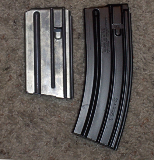
Two detachable box magazines. Left is a 20 round magazine made by Colt, right is a 30 round "High Reliablility" magazine made by Heckler & Koch.
Click on the image to enlarge.
Image licensed under GNU Free Documentation License v 1.2 or later, by user Raygun on wikipedia.

The video below shows how to interchange detachable magazines on a pistol.


The invention of the box magazine is generally credited to two Scottish born Canadian brothers, James Paris Lee and John Lee. In 1878, they invented a rifle, whose box magazine design was used by the Lee-Metford and later, the Lee-Enfield rifles.

The original Lee Rifle prototype. Click on the image to enlarge. Public domain image.

The above image shows the first Lee rifle prototype. The box magazine is visible under the stock, just ahead of the trigger guard. The magazine that this rifle uses is an internal magazine.

Box magazines store their cartridges in columns, either one above the other (single column a.k.a single stack magazine) or in a zigzag manner (double column a.k.a double stack magazine or even quadruple column a.k.a casket magazine). The images below show the different styles of magazines.

A single column (single stack) magazine. Click on the image to enlarge.
Image licensed under the Creative Commons Attribution 3.0 Unported License from Martin Meise at Wikipedia.

A double column (double stack) magazine. Click on the image to enlarge.
Image licensed under the Creative Commons Attribution 3.0 Unported License from Martin Meise at Wikipedia.
A quadruple stack magazine for a Spectre M4 submachine gun. Click on the image to enlarge.
Image licensed under the Creative Commons Attribution-Share Alike 2.0 License from Evers at Wikipedia

Box magazines can be made of either metal or plastic. Plastic magazines may be made of a transparent material, which allows the user to easily see how many cartridges are left in the magazine.

Box magazines are loaded by hand, or more quickly by devices such as stripper clips, en-bloc clips, speed loaders etc. We already studied stripper clips and en-bloc clips two posts ago. In the images below, we see two other speed loading devices designed for M-16 magazines:


A bench loader and a strip loader for M16 magazines. Click on the images to enlarge.
Images are in the public domain.

People who use pistols may be familiar with a device called a "thumb saver", which is sometimes used to load magazines. Basically, a box magazine is usually pretty easy to load by hand, except for when the magazine is almost full. The last couple of cartridges are usually very hard to push in manually and thumb savers reduce the effort required to do this (and prevent sore fingers and thumbs!).

Box magazines have a number of advantages over tubular magazines:

  1. They can safely hold cartridges that have spitzer-type (pointed) bullets, which tubular magazines cannot do.
  2. They can hold a fairly large number of cartridges, compared to tubular magazines. 30 round magazines are very common for rifles, for instance.
  3. If they are made of plastic, they can be made transparent so that the user can see how many cartridges are left in the magazine. Since tubular magazines are generally enclosed by the stock of the firearm, the user cannot see how many cartridges are left in a tubular magazine.
  4. The user can preload a bunch of magazines in advance and can quickly switch between them (at least, for detachable box magazines).
  5. It is easier and faster to load or unload a box magazine than a tubular magazine.

Because of these numerous advantages, box magazines are the most common type of magazine used by modern pistols, submachine guns and rifles today.


Capsule Magazines

$
0
0
In our last post, we studied a type of magazine that is widely used in modern firearms, the box magazine. In today's post, we will study a type of magazine that came out around the same time as the box magazine, but is not seen in much use today. We are talking about the capsule magazine.

There is really only one somewhat famous model of rifle that ever used the capsule magazine. However, this rifle was pretty influential and was adopted as the military rifle of three countries: Denmark, Norway and the United States of America. This rifle was the Krag-Jorgensen rifle.

The Krag-Jorgensen rifle was designed in 1886 by a Norwegian officer Ole Herman Johannes Krag and a Norwegian master gunsmith, Erik Jorgensen. Captain Krag had already had some experience in designing firearms at this point, as he had designed the Krag-Petersson rifle (with Swedish engineer Axel Petersson) in 1876, which was already used by the Norwegian navy. The earlier Krag-Petersson rifle, as well as the Jarmann rifle (used by Norway and Sweden) both used tubular magazines and Captain Krag was somewhat dissatisfied with the reliability of the tubular magazine. Therefore, he enlisted the help of a master gunsmith called Erik Jorgensen to design a new type of magazine for a new rifle. The result was the capsule magazine.

The interesting thing about this magazine is that unlike the tubular magazine, which is a straight tube that is generally positioned under the barrel, this magazine wraps around the action of the rifle. The cartridges in a capsule magazine are loaded parallel to each other, similar to a box magazine and unlike a tubular magazine. The following pictures will make it clear how the magazine works.


Side view and sectional view of the Krag Jorgensen rifle. Click on the images to enlarge. 
Images are in the public domain.

In the above  images, we see two views of the rifle, a sideways view and a sectional view of the magazine. The second picture makes it clear how the cartridges wrap underneath the action and are loaded into the chamber.

There is an opening on the right side of the rifle, which is covered by a hinged door. Cartridges are pushed one at a time, through this opening and the spring and follower push the cartridges around and up into the action. A nice feature of this type of magazine is that it is easy to refill it, and unlike the internal box magazines we saw in the previous post, the user does not need to lock the bolt back to do this.

The original Krag-Jorgensen rifles were designed to hold 10 cartridges in the magazine. In 1886, the Danes held a trial for a new military rifle and an early Krag-Jorgensen rifle was submitted as an entry to the competition. The feedback of the Danish military revealed the need to lighten the rifle and therefore, the designers reduced the magazine capacity to 5 cartridges.

One more interesting feature of this rifle is that it has a magazine cut-off lever, which can be seen in the second picture. The reason for this lever is because of the military thinking of the day. Generals believed that if they gave soldiers the capacity to rapidly fire at long ranges, they would spend less time aiming carefully and would waste ammunition. However, if there was a need to charge at the enemy, or to defend against an enemy's charge, then a rapidly firing weapon was needed. This is why the cut-off lever was included. When the lever is flipped up, it blocks the cartridges in the magazine from being picked up by the bolt action. This means, the soldier has to open the bolt manually, load a single cartridge in the chamber, push the bolt back and use it as a single-shot weapon. When the cut-off lever is flipped down, it allows the bolt to pick up a new cartridge from the magazine upon closing the bolt. The military thinking was that soldiers could load the magazine up fully, but flip the cut-off lever up and use the rifle in single shot mode when firing at enemies at long distance, thereby conserving the ammunition stored in the magazine. If they needed to charge an enemy or defend against an enemy charge, they could flip the cut-off lever down and use the ammunition stored in the magazine for extra firepower.

A Krag-Jorgensen Model 1892 rifle. Click on the image to enlarge. Public domain image.

The Krag-Jorgensen was selected by the US military in 1892 and served until 1903, when it was replaced by the Springfield M1903, which could handle more powerful ammunition and could be loaded faster via stripper clips. So far as your humble editor has heard, the Krag-Jorgensen was the sole user of the capsule magazine and no other firearm has used this unique type of magazine.

In the next few posts, we will study other types of magazines.


Drum Magazines

$
0
0
In our last post, we studied the capsule magazine. In today's post, we will study a type of magazine that is known for its capacity. Today's object of study will be the drum magazine.

This type of magazine is a flat cylindrical shape, similar in shape to a drum, which is why it is called a "drum magazine". These magazines can generally hold a lot of cartridges inside them. The gun that was originally associated with the drum magazine was the Thompson submachine gun, otherwise known as the "Tommy Gun", "Chicago Typewriter", "Trench Broom" etc., which was first produced in 1918.

A Thompson submachine gun with a drum magazine attached.
Click on the image to enlarge.

The above image shows a Thompson submachine gun with the drum magazine attached. Now let's look at the mechanism from the inside:
Drum magazine internals. Click on the image to enlarge.
Image licensed under the GFDL from user Hmaag at wikipedia

The above image shows both drum and box magazines, but we will only consider the drum magazine here. This drum magazine has a coil spring, which is wound up using a key. The unwinding coil spring powers a spider gear assembly, which is used to push the cartridges along a spiral path towards the opening on the top of the magazine. To load this type of magazine, the key is removed and the top cover of the magazine is lifted up to expose the interior of the magazine. Then cartridges are filled into each of the compartments, first filling the outer ring and then moving on to the inner ring. Then the magazine cover is placed back into position and the key is wound up to a certain number of clicks, depending on the capacity of the magazine.

The Thompson submachine gun is designed to use four different types of drum magazines of different capacities. The L-type drum magazine (which is the most common) holds 50 cartridges, the C-type drum magazine (which is much rarer) holds 100 cartridges, the XL-type drum magazine holds 39 cartridges and finally, the X-type drum magazine that holds only 10 cartridges (this was designed due to firearm laws enforced at that time.) As you might have possibly guessed, the names L, C, XL and X are because they are the Roman numerals corresponding to the magazine capacities.

Th spider gear type of drum magazine design is pretty commonly used in other firearms as well, most notably, the AK family of firearms (e.g. AK-47, AKM etc.)

Another common type of drum magazine is the Beta C-Mag, designed by Jim Sullivan and manufactured by the Beta Company. 

Schematic illustrations of Beta C-Magazines, filled and empty. Click on images to enlarge.
Images licensed under the Creative Commons Attribution 3.0 Unported license by Martin Miese at wikipedia.

The magazine has twin drums with a feed clip assembly in between. The feed clip assembly is interchangeable to accommodate specific firearms. There are a few spacer cartridges in the magazine (illustrated above in red, black and blue colors) and these are actually part of the magazine and do not get loaded into the firearm. Their purpose is to push the actual cartridges to the top of the feed assembly as the magazine is emptied. The top spacer cartridge (which is colored red in the images above) is tapered, so that when the firearm fires its last round, the bolt closes without picking up the spacer cartridge. To load this type of magazine, new cartridges are pushed in at the top of the feed clip and the cartridges are evenly split into the two drums. The rotors in the two drums are driven by springs, which push the cartridges out of the magazine as needed. 

An 82nd Airborne Division paratrooper firing his M4 equipped with a Beta C-Mag. Click on the image to enlarge. Public domain image.

A Beta C-Mag can hold up to 100 cartridges. Unlike the earlier drum magazine we studied, this one is a lot more compact because of the double drum design and also distributes the weight better. This type of magazine is available for several firearm models, including the M16 family, M14 rifle, FN FAL, Steyr AUG etc.

In general, drum magazines have much higher capacities compared to box magazines. However, they have been prone to jamming problems and they also tend to increase the weight and alter the balance of the firearm.


Pan Magazines

$
0
0
In our last post, we studied the drum magazine. In today's post, we will study another type that looks very much like the drum magazine, but operates a bit differently. Today's object of study will be the pan magazine.

The pan magazine is a flat cylindrical shape, similar in shape to a drum magazine. However, if you look at the previous post, drum magazines are mounted from below the gun. A pan magazine, on the other hand, is mounted on top of the gun and uses the force of gravity to drop cartridges into the action. One more difference is that the cartridges in a pan magazine are arranged perpendicular to the axis of rotation, whereas the cartridges in a drum magazine are arranged parallel to the axis of rotation. The easiest way to understand it is via some pictures.

A pan magazine from a Lewis gun. Click on the image to enlarge.

As you can see from the above image, the cartridges are arranged like the spokes of a wheel in a pan magazine. Compare this to how the cartridges are arranged in a drum magazine, as seen in our previous post.

One of the first firearms to feature a pan magazine, was the Bira gun, which we studied many months ago.

A Bira Gun. Click on the image to enlarge.

The flat circular object that you see on top of the gun is the pan magazine. In the Bira gun, this magazine is designed to hold .577-450 Martini cartridges in two layers of 60 cartridges each, giving the magazine a capacity of 120 cartridges. As the crank (which can be seen on the side at the rear of the gun) is turned, the magazine is rotated via a ratchet mechanism. There is a stationary plate at the bottom of the pan, which has a slot in it, big enough for a cartridge to fall through into the action.

Another gun that features a pan magazine was invented in 1898 by Howard Carr, a well-known shooter (he once held a world-record for pistol shooting), and manufactured by the San Francisco Arms Company. The details of his patent may be viewed here.

Image from Howard Carr's machine gun patent claim. Public domain image. Click on the image to enlarge.

In the above drawing, note how the cartridges sit on top of each other in the magazine. This allows the magazine to hold a large number of cartridges.

Some other guns that feature pan magazines are the Lewis gun, the Bren light machine gun, the Degtyarev light machine gun and the American-180 submachine gun. 

A Lewis gun. Click on the image to enlarge. Public domain image.

A Degtyarev gun. Click on the image to enlarge. Image copyright Polish Ministry of National Defense and used with permission.

In the case of the Bira gun and the Lewis gun, the pan magazine has notches or teeth on the outside of the magazine cover, which can be driven by a ratchet and pawl mechanism. In the case of a Bren gun or an American-180, the magazine is rotated by unwinding a circular spring.

Like drum magazines, pan magazines can hold a pretty large number of cartridges. The Bira gun's capacity is 120 cartridges, the Howard Carr machine gun magazine holds 310 cartridges, the Bren magazine holds 100 cartridges, the Lewis gun holds 47 or 97 cartridges, the Degtyarev holds 47 or 60 cartridges and the American-180 can hold 165, 177, 220 or 275 cartridges, depending on the model of magazine. Since a pan magazine sits flat on top of the gun, this means the gun doesn't take up too much vertical height and this allows the soldier to lie prone on the ground without exposing himself much.


Rotary Magazines

$
0
0
A few posts ago, in our study about capsule magazines, reader William Reichlinger posted an interesting comment asking whether a 1941 Johnson rifle uses a capsule magazine or not and that wikipedia mentions that it is a rotary magazine and whether it is a subclassification of a capsule magazine or not. Therefore, in today's post, we will study all about the rotary magazine.

To answer the question briefly, a rotary magazine uses a different feed mechanism than a capsule magazine. A capsule magazine has a spring and follower to push rounds from the magazine into the chamber and it is always a fixed magazine. A rotary magazine, on the other hand, can be either a fixed or detachable magazine and the feeding mechanism consists of a sprocket (or sprockets) that is rotated by a torsion spring. The cartridges fit between the teeth of the sprocket and as the sprocket rotates, it feeds the rounds to the chamber. The figure below shows the various parts and the completed assembly of a rotary magazine.

Parts of a rotary magazine. Click on the image to enlarge.

The cartridges fit between the teeth of the two sprocket wheels and are fed into the chamber of the firearm, powered by the tension of the torsion spring.

One of the early designs for a rotary magazine design is by Otto Schonauer in 1885. Otto Schonauer was a protege of the famous German firearms designer, Ferdinand Mannlicher and his rotary magazine design appeared in a turnbolt Mannlicher .43 caliber rifle design in 1887. However this rifle was not very successful and the magazine was not perfected yet. A much improved rotary magazine was featured in the Mannlicher-Schonauer M1903 rifle design, which was very successful.

Diagram of a Mannlicher rotary magazine by itself. Click on the image to enlarge
 A Mannlicher rotary magazine attached to a rifle. Click on the image to enlarge.

Meanwhile, over in the United States, Arthur Savage was also working on a rotary magazine design, which he perfected in 1893 and obtained a patent for it. This design was used in the Savage M1895 and Model 99 rifles.

Patent documentation for the Savage Model 99 rotary magazine. Click on the image to enlarge. Public domain image.

Interestingly, this rifle's rotary magazine design also includes a counter that shows the user how many cartridges are left in the magazine. It must be noted that not all Savage Model 99 rifles have this rotary magazine, as some later versions feature a box magazine instead. The Model 99 was produced by Savage for nearly 100 years (1899 - 1998) and has been chambered for many different cartridges.

Another firearm that uses a rotary magazine is the Johnson M1941 rifle, which we mentioned at the start of this post. This rifle was invented by Melvin Johnson and the magazine design is shown below from his patent application:


Click on the images to enlarge. Public domain images.

The entire Johnson patent document may be viewed online here.

Some other firearms that use this sort of magazine include the hugely popular Ruger 10/22 rifle and the Steyr SSG 69 rifle.

A rotary magazine used by a Ruger 10/22 rifle. Click on the image to enlarge. Public domain image.

The above image shows a rotary magazine used by a Ruger 10/22 rifle. This particular model holds 10 cartridges and is made of clear polycarbonate plastic and allows the user to see how many cartridges are left in the magazine. Many American readers of this blog will recognize this type of magazine because this is what comes with the standard model of the Ruger 10/22 rifle. For non-American readers, the Ruger 10/22 is one of the most popular rifle models in the US since 1964, because of its affordable price, ability to be customized, widespread availability of third party components and low cost of ammunition, and it is often the first rifle for many Americans.

Rotary magazines typically have a capacity of around 5 to 10 cartridges, which means they don't hold as many cartridges as some of the other magazine types we studied earlier. On the other hand, many rotary magazine designs fit right into the magazine's stock, without protruding out like a box magazine or a drum magazine do, which makes them much more convenient. In some rifles, the rotary magazine fits right where the center of gravity of the rifle is. Rotary magazines can also use spitzer type pointed bullets safely. In fact, the Savage Model 1895 was one of the first lever-action rifles to use spitzer bullets, as previous lever-action rifles used tubular magazines, which as we saw earlier, are not safe to use with centerfire cartridges using spitzer bullets.

Helical Magazines

$
0
0
In our last article, we studied the rotary magazine. In today's article, we will study a magazine that was invented more recently. Today's object of study will be the helical magazine.

The helical magazine was invented by Michael Miller and Warren Stockton in 1985 and produced by the California Instrumentation Company (later known as "Calico"). Interestingly, the California Instrumentation Company was originally known for manufacturing specialized instrumentation for the petroleum industry, but since they already had experience in tooling and engineering, they didn't have too much trouble manufacturing firearms. By about 1988 or 1989, they had the bugs ironed out and started producing them in quantity, along with firearms designed to use these magazines.

Image from the patent application for the helical magazine. Click on the image to enlarge. Public domain image.

The concept behind the helical magazine is to arrange the cartridges in a helical spiral, as shown by figure 2 above. A drive spring rotates the drive member and pushes the cartridges into the chamber. The figure below shows a cutaway of how the magazine works:

Cutaway of a helical magazine on a Calico firearm. Click on the image to enlarge.

The full patent details for this type of magazine may be viewed here. The nice feature of this type of magazine is that it can hold a lot of cartridges in a pretty compact space.


Unfortunately for Calico, the Federal Assault Weapons ban came into effect in 1994 (and was in effect until 2004). This law stated that no firearms manufacturer could produce magazines with greater than 10 cartridge capacity. Therefore, Calico could not really sell their firearms during this period because their biggest selling point was that the magazine could hold a lot of cartridges. Only after 2004 when the law was changed, could they restart manufacturing their firearms. Calico now offers firearms that have 50 and 100 cartridge capacities.

The idea of a helical magazine was copied by other countries, most notably by Russia, China, Hungary, North Korea etc.. The Russian Bizon submachine gun is one such weapon that uses this concept.

Bizon submachine gun. Click on the image to enlarge.
Image is licensed under the Creative Commons Attribution-Share Alike 3.0 Unported license by Vitaly Kuzmin

The above image is a Russian Bizon submachine gun. The word Bizon is the Russian word for "Bison". The long cylindrical tube that you see under the barrel in the image above is the helical magazine. It comes in two versions: one is chambered for the 9x18 mm. Makarov cartridge and the other model uses the popular 9x19 mm. Parabellum cartridge. Magazine capacity is 64 cartridges for the Makarov cartridge and 53 cartridges for the Parabellum cartridge. Incidentally, two of the designers of this firearm have very famous parents as well: Viktor Kalashnikov (son of Mikhail Kalashnikov, designer of the AK-47) and Alexi Dragunov (son of Evgeny Dragunov, inventor of the SVD sniper rifle).

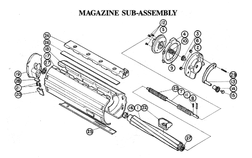
Compared to box magazines (which can hold about 30-40 magazines before becoming unwieldy), helical magazines can hold a lot more cartridges in a relatively compact space. However, unlike drum magazines, a helical magazine does not stick out of a firearm so much as to affect the balance and ergonomics. On the other hand, helical magazines have a lot more parts than other magazine types (as you can see by the image of the magazine sub-assembly above), so disassembling one can be complicated. Also, loading and unloading the magazine must be done one round at a time, which means it can take a while to do this.


Viewing all 263 articles
Browse latest View live