Quantcast
Channel: Firearms History, Technology & Development
Viewing all 263 articles
Browse latest View live

How do Firing Mechanisms Work - II

$
0
0
In our last post, we saw a movie showing how a firearm could implement a mechanism to shoot in semi-automatic and full automatic modes. Of course, the video showed one particular way to achieve this, but there are other ways as well.

In today's post, we will study another mode of firing: burst mode. Burst mode is an intermediate between semi-automatic and full automatic firing modes. In semi-automatic mode, the weapon will fire one round per trigger pull and the user has to release and pull the trigger again to fire the next shot. In full automatic mode, the weapon will continue to fire automatically as long as the trigger is held down and there is ammunition available in the magazine. While full automatic firing provides a lot more firepower than firing in semi-automatic mode, it also tends to waste a lot more ammunition, especially if soldiers are inexperienced and hold down on the trigger for longer than necessary. The recoil from firing in full automatic mode also leads to inaccuracies. Burst mode provides a compromise between these two firing modes. When a firearm selector is set to fire in burst mode, it will fire up to a set number of rounds (usually 2 or 3 rounds) per trigger pull. After that, the user has to release and pull the trigger again to fire the next set of rounds and so on.

In Vietnam, the US military found that new soldiers often ran out of ammunition in combat, because they had set their M16 rifles in full automatic mode and shot their entire supply of ammunition in a few seconds (and often without hitting their targets). Therefore, they requested that the M16A2 model remove the full automatic mode option and implement a burst mode instead. Their studies showed that a three-round burst provides the best balance between firepower, accuracy and conservation of ammunition. This is why the M16A2 and M16A4 models and the M4 carbine models have a three-round burst mode.

A person named "Stealth the Unknown" has prepared a great video showing how these different firing modes were implemented on the M16 family of rifles:


In the case of M16 models, the burst mode is implemented by a rotating cam. The same video also describes how the mechanism works for semi-automatic and full automatic modes.

The same author also prepared a second video answering some follow-up questions about this mechanism.


For instance, in a M16, if the user releases the trigger before a three round burst is complete, then the next trigger pull will only fire 1 or 2 rounds. This is because the M16's cam mechanism does not reset when the trigger is released. In some other firearms, the mechanism resets every time the trigger is released and therefore the next trigger pull will fire the full number of rounds. The author of the video also goes into an interesting theoretical design where he designed a selector with multiple burst firing modes as well as a semi-automatic and full automatic modes.

Happy viewing.


How do Firing Mechanisms Work - III

$
0
0
In our last couple of posts, we saw a couple of examples of semi-automatic, full automatic and three round burst mechanisms. The first video was prepared by the US Army to train soldiers. As it turns out, the Army had actually prepared a set of videos. The first in the series showed an example of a bolt-action firearm in action. We will study that video in today's post:


Interestingly, the video shows a hammer fired and a striker fired mechanism and also deals with extraction and ejection mechanisms, as well as loading new ammunition from a box magazine.

Happy viewing.

How do Firing Mechanisms Work - IV

$
0
0
In our last post, we saw a video that showed the basics of a bolt-action firearm, A bolt action is in the class of manually operated firearm actions. In today's post, we will study a few different classes of firearm actions, which we have already studied the basics of many months ago.

  1. Manual bolt action.
  2. Gas operated action.
  3. Blowback action.
  4. Recoil action.
In the above links, we studied these actions using some illustrations and also studied some specific variations of these actions (e.g.) short recoil action, long recoil action, direct gas impingment, short stroke gas operation etc. We also studied examples of weapons that used these different actions.

Thanks to the efforts of the US Army, we actually have a movie that illustrates the basics of all of these actions.


The video clearly illustrates how the various actions work, far better than static images do. Happy viewing!


Trigger Mechanisms of the AR-15 and the M16

$
0
0
A little while back, we studied how the trigger mechanisms of the AR-15 and M16 rifles work, complete with a video with animation explaining the concepts.

In today's post, we will look at a couple of videos that show the actual parts, instead of a 3-D Solidworks animation.

First up, an explanation of the AR-15 trigger mechanism:


Next, we have another video, that discusses the trigger mechanism of a M16 and compares it to that of an AR-15


Note that the M16 trigger mechanism being discussed is the M16-A1 model, which is capable of firing in semi-auto (single shot) and full-auto modes (unlike the M16-A2 and A4 models, which can fire in semi-auto and 3-round burst modes only). The AR-15 is capable of semi-auto fire only.

Happy viewing.

M16 Operation and Functioning Cycle

$
0
0
In our last post, we studied the similarities and differences between the AR-15 and M16 trigger mechanisms. Today's post will be another educational movie courtesy of the US Army (your tax dollars at work!). We will study the methods of operating a M16 rifle and its functioning cycle.

Today's movie was produced sometime in the early 1960s and describes the operation of the M16 rifle, specifically the earlier models. It also shows the functioning cycle of operation of a M16 rifle (i.e.) Firing, Unlocking, Extracting, Ejecting, Cocking, Feeding, Chambering and Locking and describes in detail how each stage works.


Note that this movie is pretty old, it actually refers to the rifle as the XM16E1. This is the first model of the M16 family that was adopted by the US Army. The earlier M16 rifle model was first adopted by the US Air Force, but the US Army insisted on a forward assist lever to be added to the rifle and therefore, the Air Force model was called M16 and the US Army version was called XM16E1 and later renamed to the M16A1 model in 1967. Also, in the early days, M16 magazines only held 20 cartridges and this can be seen in the movie as well.

Happy viewing.

How to Measure the Chamber Dimensions

$
0
0
Assume that you've just purchased a firearm and brought it home and found that you don't know what cartridges the firearm takes. This could be because the firearm was manufactured a long time ago, when manufacturers did not stamp the cartridge dimensions on the outside of the weapon. Or, the previous owner could have a custom barrel made for the firearm. Perhaps a previous owner liked to experiment with wildcat cartridges. Or perhaps, you would like to measure the dimensions of the chamber to make sure it isn't too worn out.

As you can see, there are plenty of reasons why someone might need to measure the dimensions of a firearm chamber. So how is it done? We will study that in this post.

One of the most common and reliable ways of measuring chamber dimensions is to use a metal alloy called "cerrosafe chamber casting alloy". This is an alloy made of 42.5% bismuth, 37.7% lead, 11.3% tin and 8.5% cadmium. Cerrosafe alloy was originally used to produce castings of toy soldiers and because of its low melting point, it was also used for fuse links in fire sprinkler heads.

A bar of cerrosafe alloy. Click on the image to enlarge. Public domain image.

Cerrosafe has some properties that make it very useful for the job of measuring chamber dimensions:

  1. It is relatively cheap to buy and easily available. A bar of cerrosafe weighing 1 lb. (0.45 kg.) can be purchased for prices ranging from $25 to $45 or so, from various sources.
  2. It is generally reusable, unless the user overheats it too much. Therefore, the alloy can be reused multiple times for many years.
  3. It has a low melting point and melts at temperatures between 158 to 190 degrees Fahrenheit (or 70 to 87.77 degrees centigrade). Note that this is below the boiling point of water (212 degrees Fahrenheit or 100 degrees centigrade). This means it can be melted by using devices commonly found in every kitchen or garage (e.g.) stoves, hot plates, blow torches, small lamps, a double boiler etc. This also means that hobbyists can use it without purchasing any special equipment.
  4. An unusual property of cerrosafe is the way it shrinks and expands as it cools down. Initially, the cerrosafe shrinks slightly during the first few minutes of cooling, just like any other normal metal or alloy does. This makes it easier to remove from a firearm chamber. However, after about 30 minutes have passed, it starts to expand while cooling. After about an hour or so, it returns back to about the original dimensions of the chamber and after about 4 days (96 hours), it expands to slightly larger than the dimensions of the chamber it was cast in (it expands about 0.0025 inches per inch of size after 96 hours, which is actually pretty negligible).
  5. One more useful property of cerrosafe is that it does not bond itself to the barrel metal like plain lead or tin do. This also makes it easier to extract out of the barrel.
In case the user thinks that cerrosafe is too expensive, there is another product made by Rotometals Inc., called Rotometals chamber casting alloy. This is practically the same composition as cerrosafe, but doesn't come in a nice stamped bar with letters on it, but is sold as a conical ingot instead. However, it has identical properties as cerrosafe, but costs about 50% less (A 1 lb. ingot of  Rotometals chamber casting alloy only costs about $15 to $20 from various sources).

An ingot of Rotometals chamber casting alloy. Click on the image to enlarge.

The following table shows how cerrosafe (or rotometals) chamber alloy's dimensions change with time, as it gradually solidifies.

TimeContraction/Expansion per inch
2 minutes-0.0004 inches
6 minutes-0.0007 inches
30 minutes-0.0009 inches
1 hour0.0000 inches
2 hours+0.0016 inches
5 hours+0.0018 inches
10 hours+0.0019 inches
24 hours / 1 day+0.0022 inches
96 hours / 4 days+0.0025 inches
200 hours+0.0025 inches
500 hours+0.0025 inches

As you can see, the alloy initially shrinks for the first 30 minutes or so, then it starts to slowly expand. After approximately 1 hour, it returns back to the original dimensions of the chamber and the alloy continues to expand, until about 4 days later, when it reaches its maximum size.

So how does the user measure the dimensions of a chamber using this alloy then?
  1. First the user disassembles the firearm as needed, to get access to the chamber of the firearm.
  2. Next, the user cleans the barrel and puts a small amount of oil in the chamber and then pushes a cleaning patch into the barrel so that it is just ahead of the throat of the barrel. The cleaning patch serves to block the barrel after the chamber.
  3. The cerrosafe (or rotometals) bar is heated until it melts. It is only necessary to ensure that the bar is not directly heated by open flame. This means it can be heated in a small iron ladle or coffee can, using a stove, electric hot plate, propane torch, oil lamp, candle etc. It can also be heated by placing a small container containing the cerrosafe into a larger container of water and then boiling the water. Remember that the melting point of cerrosafe is well below that of the boiling point of water.
  4. The molten cerrosafe is then poured into the chamber of the firearm, until the chamber is full. Since the melting point of cerrosafe is so low, it doesn't affect the barrel or the cleaning patch that is blocking the barrel on the other side of the chamber. The cerrosafe alloy is then allowed to cool until it turns a shiny silver color. As soon as the alloy has cooled enough that it is no longer a liquid, it can be pushed out of the chamber using a cleaning rod or wooden dowel (remember that cerrosafe initially shrinks slightly as it cools for the first few minutes, which makes it easier to push out).
  5. After about an hour, the casting expands back to the original dimensions of the chamber. It is then carefully measured at various points to determine the exact dimensions of the chamber, using a vernier caliper or a dial gauge. The user can then use these measurements to figure out what cartridge size the firearm was designed to use. Reference books that list the exact dimensions of various cartridge types are readily available, therefore the exact cartridge model may be easily determined. A good reference book that is commonly used is "Cartridges of the World".
After this, the casting can be stored somewhere until it is needed to measure the chamber of a different firearm, as the alloy can be remelted and reused multiple times.

One of the nice things about this process is that the user doesn't need to be very experienced to do this and the tools are also generally available and cheap.

Here's a movie from the one and only Mr. Larry Potterfield, showing how to use cerrosafe to measure a chamber.


Happy viewing!


The M3 Grease Gun

$
0
0
In today's post, we will study a submachine gun that was in US service for 50 years and is still used by some military forces elsewhere in the world. Today's post will study about the famous M3 and M3A1 submachine guns, more popularly known as "grease guns".

The origin of this design has to do with the onset of World War II. In Europe, the Germans had developed the MP-40 submachine gun and the British had the Sten submachine gun. Both these weapons were chambered to fire the reliable 9x19 mm. Luger cartridge. In 1941, the US Army Ordnance Board conducted some studies on the effectiveness of these weapons on the battlefield and determined that there was a need for similar weapons for the US military as well. At that time, the US military had already adopted the Thompson submachine guns (which were developed at the end of World War I) into service in 1938, but the Tommy guns were relatively expensive to manufacture. The Ordnance Board wanted a weapon that could fire the same .45 ACP cartridge of the Thompson, but which could be manufactured much cheaper and could be fired as accurately as well.

The final list of requirements included:

  1. Weapon to be made of metal completely, with largely sheet metal construction, in order to speed up manufacturing.
  2. Weapon designed to fire .45 ACP cartridges, since the US military was already using this cartridge (The Germans and British were using 9 mm. Luger cartridges for their submachine guns)
  3. Weapon to be designed for fast production, with a minimum of machining operations.
  4. Weapon to be designed to be cheap to manufacture (cheaper than the Thompson submachine gun)
  5. Weapon to be designed as reasonably accurate. It was required to demonstrate that this weapon could put 90% of shots fired in a standing position in full-automatic mode into a 6x6 foot target at a distance of 50 yards. 
  6. Weapon to be capable of firing in both semi-automatic and full-automatic modes. This requirement was later removed during development of the weapon and it was designed to fire full automatic only.
The task of designing this weapon fell to George Hyde of General Motors' Inland Division. George Hyde was actually of German descent and had emigrated to the US in 1927, whereupon he changed the spelling of his last name from "Heide" to "Hyde". He was a well known gun designer in 1941 and was put in charge of designing the new weapon. Meanwhile, another engineer named Frederick Sampson was put in charge of preparing the tooling for mass production of this weapon. During the design phase, a conversion kit was also designed, which would allow the user to quickly convert the gun from firing .45 ACP to firing the 9 mm. Luger cartridge.

The prototypes were completed in late 1942 and approved for mass production. The Guide Lamp division of General Motors (the same people that manufactured the FP-45 Liberator pistol) was put in charge of manufacturing it. While the weapon was given the official designation of "U.S. Submachine Gun, Caliber .45, M3", many people noticed that it resembled grease guns used by automobile mechanics and therefore, the new weapon was nicknamed the "Grease Gun".

The M3 Grease Gun. Click on the image to enlarge.
Image licensed under the Creative Commons Share-Alike 3.0 Unported license by Curiosandrelics

The M3 was designed to be cheap. The manufacturing cost of one of these in World War II was around $18. Only three parts, the bolt, the barrel and the firing mechanism, were precisely machined. Most of the other parts of this gun were manufactured by using metal stamping and pressing technologies. Spot welding and seam welding were used to join most of the parts together and some other parts were riveted together. These processes allowed the gun to be manufactured very rapidly and with low cost. The stock was simply made from a single steel rod, which was bent into shape. The ends of the stock were drilled and tapped, so that it could be used as a cleaning rod, as well as a disassembly tool. In the M3A1 model, the stock also had a tool welded to it, to be used to load a magazine. The safety was a projection on the inside of the ejection port dust cover, which locked the bolt into the forward or rear positions. However, since the metal around the dust cover was so thin, it could get bent easily and the safety mechanism wouldn't work any more.

The two halves of the receiver were made by stamping sheet steel and then the two halves were welded together. The bolt was made heavy and made to run on two parallel guide rods, which had twin return springs. This allowed the receiver to be made to looser tolerances. The barrel was cold swaged to save time and cost. The weapon was designed to be striker fired, with a fixed firing pin inside the bolt.

When the M3 first entered service, no replacement parts were supplied. The weapon was originally intended to be a low-cost tool that could be discarded when it ceased working. However, due to a temporary shortage of M3s in the middle of 1944, the US Army Ordnance workshops manufactured some spare parts to keep existing weapons operational. There were also a number of issues with the M3 and several improvements were incorporated into the M3A1 model, which went into service in December 1944. During the Korean war, existing M3 guns were converted to the M3A1 standard.

While it was hoped that this gun would be produced in large numbers to replace the Thompson submachine gun in US service, this did not happen and there were about three times as many Tommy guns in service than M3/M3A1 at the end of World War II.

Due to its cheap cost and portability of the weapon, it was issued to paratroopers, tank crews and truck drivers. Even though it was withdrawn from frontline service in the US military in 1957, they were still issued to tank and truck drivers and were carried by US tanks during the 1991 Gulf war. The M3A1s were finally replaced starting in 1992, with the M4 carbine. That means it served in the US military for 50 years (1942 - 1992). It is still used by military forces in other parts of the world.


The Sten Gun

$
0
0
In our last post, we saw how America adopted the M3 a.k.a the Grease Gun. In today's post, we will look at one of the guns that inspired it, the British Sten gun. This was a gun that was designed to be manufactured cheaply and easily and we will study its origins and design today.

Different Sten gun models. Click on the image to enlarge.

First, we must go back in history to Europe in the summer of 1940. German soldiers were sweeping through Belgium and France and allied troops were in a desperate situation and trapped in the tiny port of Dunkirk. The British deployed every boat and ship available to rescue the stranded Allies and in nine days (27th May - 4th June), over 300,000 soldiers (British, French, Polish, Belgian, Dutch etc.) were evacuated to England. However, this rapid evacuation also resulted in soldiers leaving their equipment behind and large amounts of firearms fell into the hands of the Germans. Shortly after that, the Battle of Britain started and many factories in England were bombed. As a result of all this, there was a shortage of small arms in Britain. The British were buying Thompson submachine guns from the United States, but the factory could not keep up with the demand (and after 1941, many of those Thompsons went to the US military, so they couldn't supply anyone else anyway). Therefore, a decision was made to design a submachine gun that could be made in England quickly and cheaply.

The task of designing this new weapon fell to Major R.V. Shepherd of the Design Department at the Royal Arsenal, Woolich and Mr. Harold J. Turpin, of the Design Department of the Royal Small Arms Factory, Enfield. The design they came up with was called the STEN. The "S" and "T" in the name came from the first letters of the designers last names (S from Shepherd and T from Turpin) and the "EN" came from the first two letters of "Enfield".

From the beginning, the aim was to design a cheap gun that could be manufactured with a minimum of machining operations. It had to be capable of being manufactured in small workshops and produced as quickly as possible. It also had to be capable of single shot and automatic fire and designed for close range fighting. It was designed to use the 9x19 mm. Parabellum Luger cartridge, which was also used by the Germans. The Sten was also deliberately designed to fit German 9 mm. magazines from the MP-38 and MP-40, so that they could use captured German ammunition and equipment if needed.

The design that they came up with was a submachine gun using a blowback mechanism and firing from an open bolt. When the weapon is cocked, the bolt remains at the rear of the weapon. When the trigger is pulled, the bolt is pushed forward by spring pressure and strips a cartridge from the magazine, chambers it and then fires it. The firing pin is fixed in front of the bolt. After the cartridge discharges, the bolt moves rearward against spring pressure and inertia of the heavy bolt and then recocks itself. The working components of this weapon are housed in a basic tubular metal receiver with a barrel on one end and a wire shoulder support welded to the other end, with a simple trigger mechanism in between

The Sten gun, Mark I

The first version of the Sten gun, the Mark I model, came with a conical flash hider and contained some wooden parts (the foregrip and part of the stock). The front pistol grip could also be rotated to make the firearm smaller and therefore, easier to pack. Production started in late 1940 and about 100,000 of this model were made.

Compared to the Mark I model, the Mark II model was much more stripped down. The flash hider was removed and the folding front pistol grip and all the wood were eliminated as well. This made the Mark II smaller and lighter than the Mark I model.


The Mark II variant was the most commonly manufactured model and about 2 million of these were produced. Some Mark II models were made with integral suppressors attached and were classified as Mark II (S)

The Mark III variant was even more stripped down than the Mark II model and was first produced in 1943. In this model, the receiver and the barrel shroud are made from a single tube, by wrapping a sheet steel plate into a cylindrical shape and welding the top. This model is also a bit lighter than the Mark II model.


The Sten Mark III model was the second most commonly produced model of the Sten gun family and was the most stripped down model of the series, and therefore the lightest version.

By 1944, the threat of a German invasion of Britain was over and the Sten gun quality improved. Models Mark IV and Mark V had better quality fit and finish and even came with wooden parts.

The Sten gun model Mark V

The Mark IV model was a paratrooper's model with a folding stock, but never got off the prototype stage. The Mark V model had better sights and finish and came with a bayonet attachment as well.

The Sten was designed to be manufactured quickly and easily. This is why most of the components could be manufactured by stamping sheet metal and doing some minor welding. From the beginning, many of the parts were subcontracted to small workshops, with final assembly being done at the Enfield factory. This was especially useful as the larger factories were being bombed from the air by the German Air Force, early on during the war. The design was made simpler with each generation and the Mark III model only had 47 parts. Interestingly, one of the largest manufacturers of the Mark III model was a toy company called Lines Brothers. The Sten was really cheap to manufacture and only cost about $10 to make, which was much cheaper than the Thompson submachine gun, which cost about $200 then.

While Sten guns were cheap to manufacture, they occasionally had jamming issues as well. The gun was designed to use the same magazine as the German MP-38/MP-40, so that people could reuse captured equipment. However, it also inherited the problems of the German magazine, in particular dirt could cause it to jam. In the absence of a pistol grip and forward grip in the Mark II and Mark III versions, some soldiers would hold the magazine with the supporting hand, causing it to wear out the magazine catch and cause failure to feed issues. The safety device was rudimentary and there was a danger of accidental discharge upon dropping the weapon, especially since many were crudely made. The Mark V model attempted to fix some of these issues.

The Sten was loved and hated by its users at the same time. Many didn't like its peculiar appearance and reliability (at least for the Mark II and Mark III models) and it was nicknamed the "Plumber's Nightmare" and the "Stench Gun". However, they liked its cheap cost and short range firepower. It was manufactured during World War II by many British companies, as well as workshops and factories in Canada, Australia, France, Poland, Denmark, Norway etc. It was responsible for the US manufacturing its own cheap submachine gun model: the M3 grease gun. Towards the end of World War II, even the Germans got in the act and made over 28,000 copies of the Sten gun. After World War II, many were made in small workshops Israel in 1948. The Sten gun is still in use in some countries around the world.


The MP38 Submachine Gun

$
0
0
In our last couple of posts, we traced the development of the American M3 Grease Gun and the British Sten Gun. In today's post, we will study the gun that preceded them both and inspired their creation. Today, we will study about the German MP38 submachine gun.

A MP38 submachine gun. Click on the image to enlarge.

The full name of this weapon is Maschinenpistole 38 (i.e. "Machine Pistol 38"). The origins of this weapon have to do with advancements in military doctrine after World War I. It was during and after this war that military concepts such as tanks, troop carriers, paratroopers etc. started becoming popular. There was need for a rapid firing weapon that could be used from inside vehicles such as tanks and trucks, as well as carried by paratroopers. General infantry crews also had use for a small, light, rapid firing weapon to protect themselves, while transporting their heavier machine guns to other locations. The German Wehrmacht was beginning to develop its theories of lightning warfare (i.e. the Blitzkrieg), where the idea was to use rapidly moving mechanized forces on the ground, operating together with air support. The German Army Weapons Office published a requirement asking for a suitable submachine gun to be designed in 1938.

The German arms company, Erfuter MaschinenFabrik Gmbh, (translation: Erfurt Machine Factory Inc.), better known by its shorter trade name, Erma, began to develop a weapon to meet this requirement. Instead of developing a weapon from scratch, they modified an existing design that they were already working on, the MP36. The MP36 was actually a compact version of the Erma EMP (Erma Maschinen Pistol (translation: Erma Machine Pistol)).

Erma EMP. Click on the image to enlarge.

The Erma EMP was actually developed by Heinrich Vollmer, a German arms designer who had his own small arms manufacturing company. He had designed this gun in 1930, based on an earlier design he had worked on in 1925 and 1928, but his newer design used a side-feeding box magazine (a feature later seen on the Sten and Sterling submachine guns) and a telescoped return spring (a feature used in the MP38 and MP40). However, the German military stopped supporting his company in 1930 and since he didn't have the financial capability to manufacture these, he sold the design and manufacturing rights to Erma, who started producing his design in 1932 as the Erna EMP. Some of these Erma EMP guns were sold to Spain and some South American countries.

The Erma company had started to make a compact version of the EMP, which they called MP36, which was a selective fire weapon. When the requirement came from the German War Office, they took this prototype and simplified it a little more and called in the MP38. One of the requirements was to use plastics in the furniture instead of wood, and the MP38 uses bakelite for its handguards and grips. After the German War Office announced that they had accepted the design, Erma started to produce the weapon in 1938 and a couple of years later, C.G. Haenel also started producing the weapon.

The MP38 uses a blowback action and features a folding butt, which reduces its length considerably when folded. It uses the 9x19 mm. parabellum cartridge, which was also used by the Luger pistol in World War I. All the critical operating parts are contained in the receiver. There is only one mode of fire: full automatic mode. However, due to the slower rate of fire, it is possible to fire single shots by pulling and releasing the trigger quickly. The magazine holds 32 rounds and is a double column, single-feed type. Uniquely, on the underside of the barrel, there is a "lip" or "resting bar". This is designed to keep the weapon steady, when firing over the side of an open-top armored personnel carrier. The idea is that the lip latches on the side of the vehicle's wall and prevents the recoil from driving the weapon back into the vehicle's compartment. A cooling fin at the end of the barrel helps dissipate some of the heat. The pistol grip and handguard are made of bakelite plastic to save weight and this is the first submachine gun in history to feature plastic parts.

Interestingly though, the receiver of this weapon is made of machined steel instead of being stamped. Therefore, it took longer to make the receivers. So while the gun was a success, it could not be made fast enough and production only lasted a couple of years before they developed the MP40 in 1940. The MP40 was made of stamped steel and used spot welding technologies to speed up production. Production of the MP38 did continue until 1941 though.

A weakness of the MP38 and MP40 was the magazine, which tended to be affected by dirt. The same magazine design was copied by the British for their Sten gun, so that they could reuse German magazines and therefore, the Sten gun inherited the same weakness as well.

One more interesting fact is that the Allies incorrectly referred to the MP40 as the Schmeisser, named after the famous German weapons designer, Hugo Schmeisser. In reality, he had very little to do with the design of the MP38 and MP40. If anything, his sole contribution was a patent he held on the magazine, which he had actually designed for a different weapon.

The MP38 may be considered as the one of the last submachine guns that was built out of machined parts. Therefore, it has a better quality and finish, compared to the MP40 that followed it. We will study the MP40 in the next post.

The MP40 submachine gun

$
0
0
In our last post, we studied about the German MP38 submachine gun. In today's post, we will study its successor, the MP40 submachine gun.

The MP38 submachine gun was a pretty successful design and performed the tasks that it was designed for well. However, it could not be manufactured quickly because of the way that some of the parts were made (many parts were machined). The original manufacturer of the MP38, Erma, gave the design to C.P. Haenel to help with production, but even these two companies together could not meet the demand for these weapons from the German Army. As a matter of fact, they could not even meet their own production targets that they had set themselves! By 1939, the German War Office asked for changes in the production methods to speed up manufacturing.

Both Erma and Haenel were relatively smaller arms manufacturing companies, so larger companies, such as Krupp, Steyr and Merz Werke, were recruited to help. The engineers from these larger companies were experienced in modern mass production technologies and they made changes to the MP38 model to speed up its production rate. The new model was introduced in 1940 and was called the MP40.

A MP40 with the stock folded. Click on the image to enlarge.
Image licensed under the Creative Commons Attribution-Share Alike 3.0 Unported license

A MP40 with the stock extended. Click on the image to enlarge
Image licensed under the Creative Commons Attribution-Share Alike 3.0 Unported license

In the MP38, many parts were machined, which made the process of manufacturing expensive and slow. In particular, the receiver took multiple machining operations on a block of steel, to make the final product. Many of the parts of the MP40, on the other hand, was made by stamping out steel parts using dies and high speed presses and then joining the parts together by using brazing and spot-welding techniques. Only the barrel and the bolt were machined in the MP40. This made the production rate much faster. Over 1.1 million MP40 submachine guns were produced between 1940 and 1945.

Therefore, the MP38 was one of the last submachine guns to be largely manufactured with machining technologies and the MP40 was one of the first submachine guns designed specifically to be manufactured quickly and cheaply. This is why the quality and finish of the MP38 is usually superior to the MP40, but the MP40 is just as effective as the MP38.

One weakness of the MP40 is that it uses the same double-column single-feed magazines as the MP38 and therefore, it has the same issues with dirt and jamming.

The MP40 comes in multiple variants as the Germans continued to improve the design to reduce the manufacturing time. Erma, Haenel and Steyr were the main manufacturers and a number of the parts were made by other subcontractors. For instance, one of the manufacturers of the plastic grips was the German electrical giant AEG (these days, they are known as AEG/Electrolux). Krupp and Merz Werke produced a lot of the stamped parts (tubes, frames etc.) for both Erma and Haenel (Steyr produced their own stampings), Mauser Werke supplied barrels and so on.

The MP40 is really the prototype for a number of other submachine guns that have been made since. It influenced the development of the US M3 Grease gun and the British Sten gun, as both the US and the UK saw the need for a rapid-firing weapon that could be produced quickly and cheaply. It is one of the first weapons to use plastics instead of wood. The forward folding stock design was first designed for the MP 40 and later copied by other people, notably the AK family.

Interestingly, the MP40 was often referred to by Allied troops as the "schmeisser", named after the famed German designer, Hugo Schmeisser. In reality though, he had very little to do with this design, as most of it was done by Berthold Geipel and Heinrich Vollmer and later improved by mass-production specialist engineers at other companies. About the only contribution of Hugo Schmeisser to the design was the magazine, which Hugo Schmeisser had designed and patented for another weapon, but the German War Office insisted on using Schmeisser's magazine design for the MP38 and MP40. Interestingly, Hugo Schmeisser did design the MP41, which is largely a MP40, but using a wooden stock and a selector lever from the MP-28, which Schmeisser had worked on earlier.

Even though the German factories stopped producing the MP40 after World War II, they remained in service with other countries for several years since. For instance, France used the MP40 during the 1950s and 1960s and Norway still used them until about 1990 or so.


The PPSh-41 Submachine Gun

$
0
0
In our last post, we studied the German MP40 submachine gun, an influential design. In today's post, we will study a submachine gun of Soviet origin, the PPSh-41.

The PPSh-41 derives its name from the Russian name Пистолет-пулемёт Шпагина which is pronounced as Pistolet-Pulemyot Shpagina (i.e. "Shpagin Machine Pistol"). Shpagin refers to the designer of this weapon, Georgy Semyonovich Shpagin. The number -41 refers to the year that this weapon was first produced.

A PPSh-41 with a drum magazine. Click on the image to enlarge.
Image released under a Creative Commons Attribution-Share Alike 3.0 Unported license by Lposka

The gun was nicknamed the "Peh-Peh-Sha" (after the Russian pronunciation of the first letter of each word), or sometimes as "Papasha" (the Russian word for "Daddy"). During the Korean war, US and UK forces who encountered this in the hands of North Koreans and Chinese troops, nicknamed this the "burp gun" on account of the "brrrap" sound it produces when firing in automatic mode.

The origins of this weapon have to do with two reasons. First, when the Soviets fought against Finland in the Winter War of 1939-40, they found that Finnish forces armed with Suomi KP-31 submachine guns could take on superior numbers of Soviet forces fighting with bolt-action Mosin-Nagant rifles at close quarters. The Soviets already had a submachine gun of their own, the PPD-34, but it was hard to produce economically and quickly. Many of the metal parts of the PPD-34 were produced by milling and machining operations, which made it take a long time to produce.

Then, in the summer of June 1941, the Germans launched Operation Barbarossa and invaded the Soviet Union. A large number of Soviet small arms as well as a number of the factories capable of manufacturing small arms, fell into German hands. The Soviets needed a weapon that could be produced quickly and without the use of sophisticated manufacturing technologies.

Enter Georgy Shpagin, a son of a Russian peasant, who had started off life as a carpenter, before being drafted into the Russian army and becoming a gunsmith and later a weapon designer. He took the PPD-40 (an improved version of the PPD-34) as the starting point of his design. While the PPD-40 used mostly machined parts, his new PPSh-41 design largely relied on stamped steel parts. Most of these parts could be manufactured by unskilled workers using equipment that is commonly seen in small workshops and automobile repair garages. Parts were joined together by welding. The PPSh-41 design used less parts than the PPD-40 and could be manufactured in about half the time it took to make a PPD-40. Only the barrel needed a little more sophisticated factory equipment to manufacture and even this was simplified, as will be discussed shortly.

The cartridge used for his weapon design was the 7.62x25 mm. Tokarev pistol cartridge, which was already in service with Soviet forces for some years previously. To simplify the production of barrels, he often used existing barrels designed for the Mosin-Nagant M1891 rifle, which were already bored for 7.62 mm. A single long M1891 barrel would be cut into two shorter barrels for the PPSh-41 as they both use 7.62 mm. diameter cartridges, and then each shorter barrel would have a chamber machined to accept the 7.62x25 mm. Tokarev cartridge. The barrels were chrome lined for extra reliability, but most of the other parts were much more cheaply produced.

The weapon itself fires from an open bolt using the blowback action (similar to all the designs we studied in the last few posts). Earlier models had a selector lever to select the firing mode and later models were designed to fire in full automatic mode only. The firing rate of this weapon is about 1000 rounds per minute, which is the highest of all the submachine guns during World War II. The receiver is hinged to make disassembly and cleaning the weapon in the field easy to do. The chrome lining in the barrel enables it to use corrosive ammunition and not be cleaned for a while in the field.

The first prototypes went into production in November 1941 and by the spring of 1942, the factories were making them at an incredible rate of 3000 per day and by the end of 1942, over 1.5 million of these were made.

Initially, the PPSh-41 was designed to use a drum magazine of 71 round capacity, which was an exact copy of the Finnish Suomi KP-31 submachine gun that the Soviets had encountered in the Winter War. The drum had a spring loaded feed mechanism that the user would have to wind up like a watch to use. However, the drum magazine had reliability issues if it was loaded to its full capacity of 71 rounds and therefore, users would often load less than 64 or 65 rounds to avoid this problem. The drum magazine was also made of a thin sheet metal of 0.5 mm. thickness. This meant that it was pretty easy to bend, which could also cause feed failures. Also, the springs inside the drum magazines would often weaken after a while and make feeding unreliable. On top of that, it took a long time to load a drum magazine. Therefore, newer versions of the PPSh-41 were supplied with 35 round box magazine instead, after about 1942.


A PPSh-41 with a box magazine. Click on the image to enlarge.

The box magazines were easy to carry around in pouches and more reliable than the drum magazines. The thickness of the metal used to make magazines (both box and drum magazines) was later changed from 0.5 mm to 1 mm., which made them much harder to bend accidentally. Many infantrymen would carry one drum magazine in the gun and several box magazines in pouches.

The Soviets made about 6 million of these weapons by the end of World War II. Some of these were later gifted to other communist countries and some African countries. The design of the PPSh-41 was also shared with some countries, most notably, the North Koreans and the Chinese, who made their own versions of this weapon during the Korean war. The Chinese also gave their design to the Vietnamese, who made their own version during the Vietnam war. US and UN troops who faced this weapon in Korea and Vietnam nicknamed this the "burp gun" on account of the noise it made when firing. The weapon still remains in use by some irregular forces around the world.


The Suomi KP/-31 Submachine Gun

$
0
0
In our last post, we had studied about the Soviet PPSh-41 submachine gun. In today's post, we will study one of the main inspirations for the PPSh-41, the Finnish-made Suomi KP/-31.

During World War I, the German designer, Hugo Schmeisser had developed the MP-18 submachine gun, which his employer, the German manufacturer, Theodor Bergmann, started to produce in his factory by 1918 and about 10,000 were made before the war ended soon after. This weapon was the first practical submachine gun used in combat (though not the world's first submachine gun). Even though this weapon was only used for a short period of time, it gained such a reputation that the treaty of Versailles explicitly specified submachine guns among the list of weapons banned from the German military. One of the weaknesses of the MP-18 was its snail-drum magazine, so shortly after World War I, Hugo Schmeisser improved the design to use box magazines. Bergmann continued to make this weapon in secret for a few years after World War I ended and about 25,000 (or 35,000 depending on who you ask) were made in total. However, since Bergmann could no longer manufacture these weapons openly, they finally sold the improved design to the Swiss company SIG (Schweitzerische Industrie-Gesellschaft) in 1920, which started to sell the improved design as the Bergmann Submachine Gun. SIG sold Bergmann models of various calibers to several countries, such as China, Japan and Finland, between 1920 and 1927, when they finally stopped making these weapons.

The Finnish army wasn't interested in this weapon initially, but the Finnish Civil Guard (Suojeluskunta) were interested and bought about 1000 Bergmann submachine guns from SIG in the early 1920s. Around this time, a talented Finnish weapon's designer named Aimo Lahti thought the Bergmann was too expensive and the reliability could be improved as well. He made his first prototype in 1921, a model that fired the .32 ACP cartridge and was about 11.8 inches (30 cm.) long and it was handmade by a blacksmith in Viiala. By 1922, he had a real working prototype (M/22) which was built by a factory with machine tools (Leskinen & Kari in Tampere). He tried to get the Finnish military interested in this weapon, but they refused because it wasn't really production-ready yet, but some members of the Keski-Suomi regiment did express interest in it. Therefore, in 1924, Lahti established Konepistooli Oy (Translation: Machine Pistol Corp.) with members of this regiment, Captain V. Korpela, Lt. Y. Koskinen and Lt. L. Boyer-Spoof. (Korpela had to leave the company later, as he was trying to sell the submachine gun to other countries without permission of the other shareholders). 

Lahti continued to make improvements and by 1924, the Finnish Defence Ministry got interested and bought about 100 submachine guns. At this time, Konepistooli Oy needed every sale they could get. By 1926, the M/26 model was introduced, which used a very unique 36-round magazine, that was not used in any weapon before then.

The Suomi M/26 submachine gun. Click on the image to enlarge.

Note the unique curved magazine shape of this weapon. The M/26 cost about half the price of the Bergmann, but it did not sell well. It also had some feeding issues and shared some of the weaknesses of the original MP-18 and Bergmann. The stock was also not strong enough for military use. Lahti succeeded in fixing these issues in his new model, the M/31.

One of the improvements in the M/31 was to remove the excess room in front of the bolt (which sometimes caused cartridges to turn sideways during loading) to prevent jamming problems. A quick release mechanism allowed the barrel to be rapidly replaced. An improved muzzle brake reduced the muzzle climb during shooting in automatic mode. The most important change was the cartridge used, as the M/31 was designed to use the 9x19 mm. parabellum cartridge that many other countries were using at that time. Because of the 9x19 mm. cartridge, two new magazines, a 20 round box magazine and a 40 round drum magazine were developed as well.

The Finnish Defence Ministry were very interested in the M/31, but Konepistooli Oy lacked the facilities for mass production. Luckily, an engineer named Oscar Ostman was a personal friend of Aimo Lahti. Ostman was the CEO of a Finnish company called Tikkakoski Rauta ja Puuteollisuusyhtio (Translation: Tikkakoski Iron and Wood Products Ltd.), which originally was a metal workshop, but also had experience in making firearm parts (like barrels for rifles and machine guns) for the Finnish military. Interestingly, the major shareholder of Tikkakoski was a German weapons dealer named Willi Daugs. Tikkakoski bought the rights to produce the M/31 from Konepistooli and called it the Suomi KP/-31 (KP standing for Konepistooli (i.e. Machine Pistol) and 31, since it was manufactured in 1931). 

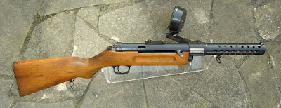
The Suomi KP/-31 submachine gun. Click on the image to enlarge.
Image licensed under Creative Commons Attribution-Share Alike 3.0 Unported license by Mbeesb

The 20 round box magazine could actually be filled with upto 25 cartridges, but it wasn't too reliable when it was filled with 25 cartridges and it was felt that 20 rounds was too little capacity for the magazine and so, the manufacture of these stopped by 1939. The 40 round drum magazine also had some reliability issues, but its bigger problem was loading it -- cartridges had to be inserted into the drum with the cartridges standing on the tips of the bullets. The slightest vibration could cause the cartridges to fall on their sides inside the magazine and the user would have to dump all the cartridges out and start from the beginning again. Luckily, Lt. Y. Koskinen, who was one of the other founders of Konepistooli Oy, came up with the design of an improved 71 round drum magazine, without Aimo Lahti's finding out until it was ready for production. This 71-round magazine was the most well known and successful magazine design of the KP/-31. In fact, the Soviets were so impressed by it, that they cloned it for their PPSh-41, as we saw in the previous article. A 50 round quadruple column casket box magazine of Swedish design was also made for the KP/-31, but this magazine proved vulnerable to small dents and therefore, it was mostly issued with the 71 round drum magazine.

When the Winter War started, Finland only had about 4000 of these in service, but after the Winter War ended and as the Continuation war started, production had ramped up to about 1400-1500 weapons made per month. Finnish soldiers used this weapon with deadly effect against the Soviets. This weapon showed what a useful weapon the submachine gun was to modern armies and other military forces were quick to adopt this concept as well.

The KP/-31 had a number of interesting features about it. It was a blowback action using Advanced Primer Ignition. This means the firing pin ignites the primer of the cartridge, before the bolt stops into battery. The bolt's momentum keeps the cartridge case locked in the chamber until the peak chamber pressure from the gases has dropped to a safe level. Unlike later submachine gun designs, this was largely built by machining the components and therefore took longer to manufacture. For instance, the receiver was machined from a solid forged steel block. The steel used for the barrel and receiver was the best Swedish made chromium-nickel steel that was available during that time. Some of the original barrels for the pre-1931 models were made by Birmingham Small Arms (BSA) in England, but Tikkakoski started making their own barrels by 1931, and many were also supplied by the precision competition rifle manufacturer, Joonas Matarainen. Interestingly, for a submachine gun, it had a quick-detachable barrel and a barrel jacket, features that are usually only found on heavy machine guns. Also, unusually for a submachine gun, each KP/-31 was supplied with two barrels (primary and spare barrel). Each pair of barrels were machined to a very high degree of precision, so that they both had very similar dispersion and point of impact. This allowed the user to quickly change barrels in the middle of a firefight without needing to adjust the sights afterwards! Even though the weapon had a high rate of fire (around 900 rounds per minute), it was surprisingly well-balanced and controllable. 

How accurate was it, the reader asks? Factory testers would shoot 10 shots at a target in semi-automatic mode, using a simple bench rest and all 10 shots would have to hit the bullseye of the target at 100 meters distance. The following two images show the results of tests conducted by the Finnish Army during official acceptance tests.

Click on the image to enlarge.

The diameter of the center circle (the ten circle) of both targets has a diameter of 4 inches (25 mm.). The shots were made from a distance of 100 meters using a simple bench rest. The left image shows 15 rounds fired at this distance using semi-automatic mode. The right image is using a 50 round magazine fired in a single long burst at the same distance, using full-automatic mode. As you can see, the test in semi-automatic mode has a 1 MOA accuracy (and it wasn't uncommon to get sub MOA groups either). In the right image, it can be seen that 48 out of the 50 shots are within the smallest or second smallest circle.

Unlike most other submachine guns, the sights were adjustable to 500 meters distance, which was a bit optimistic, but the weapon was easily capable of hitting targets at 300 meters distance. It was much more accurate than every other submachine gun of that period (and probably even now). In the dense Finnish forests, the range of the KP/-31 was more than adequate and the large drum magazine and fast rate of fire meant it could spray more lead than practically any other automatic weapon of that time. 

One more interesting feature was the cocking handle (charging handle). It was a non-reciprocating design (i.e.) it does not move back and forth when the gun is fired (similar to that of a bolt-action rifle). The user only pulled it back once after loading a new magazine into the weapon, to cock it initially, and after that the charging handle would not move at all. Because of this feature, it didn't have a bolt handle slot and therefore, was less likely to let mud and snow enter into the firing mechanism, which led to greater reliability.

A couple of variants were made to be used inside bunkers and tanks. These had thinner barrel shrouds and no shoulder stock, using a pistol grip instead. These were designed to be used in enclosed spaces where it was necessary to fire through narrow slits. On these variants, the sights located on the left side of the weapon, to make it easier to aim through a slit. The tank version was designed with a special barrel shroud that was permanently attached to the firing port of a 6-ton Vickers tank (the T-26E model). If it became necessary for the crew to abandon the tank, the weapon could be easily removed from the firing port and normal barrel shroud attached to it to use as a regular submachine gun.

One more variant was from 1942. This variant had an "improvement" to add a muzzle brake. This model was called the KP/-31 SJR (SJR from the word "suujarru", the Finnish word for "muzzle brake" or "compensator"). This increased the length of the weapon by 55 mm. Aimo Lahti didn't like the new compensator because the oblique front end of the barrel jacket was found to be as efficient as the compensator. On the other hand, the compensator caused trouble in cold frosty weather, as powder and primer residue would get trapped in the chamber and the resulting sticky mass of condensed water, carbon and salts would stick to the breech bolt and cause misfires. On top of that, the compensator reduced the muzzle velocity a bit as well. This "improvement" enraged Aimo Lahti so much that he attempted to find out who was responsible for this change and have him charged in a military court, but to this day, the identity of the genius responsible remains a classified secret!

The Finns used this weapon against Soviet forces with great success and showed the world how submachine guns could be used in warfare by regular troops and not just as defensive weapons by truck drivers and tank crews. 

The Suomi KP/-31 had superior firepower, excellent accuracy and very high reliability. On the downsides were its weight, high production cost and slower production rate. Finnish infantry soldiers liked this weapon a lot. It was also manufactured under license in Sweden, Denmark and Switzerland and also used by other countries such as Norway, Israel, Germany etc. In 1938, the British Army conducted tests on many different submachine gun models and their Ordnance Board concluded that the KP/-31 was the best weapon by far. However, since the Finns were battling the Soviets at that time, the British concluded that they might not be available for purchase and opted for the Thompson submachine gun instead.

Incidentally, Norway used them until the 1980s and the Vatican Swiss Guard used them until the 1970s (as the Swiss made version of the KP/-31, the Hispano Suiza MP43/MP44). The tank version of the KP-31 (which was described 4 paragraphs above) was still in service in Finland through the 1980s, despite the fact that the T-26E tank that it was designed for, was decommissioned by Finland in 1959!

The MP 18 Submachine Gun

$
0
0
We have studied the evolution of different submachine guns in the last few posts, in reverse order of appearance. Today, we will study the submachine gun that started off this whole class of weapons, the MP 18 submachine gun, otherwise called the MP 18/I or the MP 18.1 or the Bergmann MP 18.1.

During World War I, tactics that were used successfully in previous wars, such as marching lines of infantry and charging cavalry, were rendered useless by artillery and heavy machine guns. With such huge firepower available, masses of infantry soldiers attempting to charge across a battlefield were practically committing suicide. This forced a change in the infantry tactics and soldiers now dug deep trenches across the battlefield and fought from inside them. New tactics were needed to fight in the trenches. For instance, battles inside trenches were fought at very short ranges because trenches were narrow and twisted. Also, since trenches often contained more enemy soldiers defending it than the attackers, it was necessary to clear the trench before the defenders could mount a counter-attack. What was needed was a small caliber weapon with a high rate of fire, but small enough to be used in narrow trenches and light enough to be carried by a single infantry man.

Heavy machine guns had a high rate of fire, but were heavy, required multiple people to move them and needed a good amount of room to operate. Besides, the range of a heavy machine gun did not matter much inside a trench. Pistols and revolvers were small and light, but didn't have a high enough rate of fire or enough ammunition capacity. Rifles were also light compared to heavy machine guns, but were longer (and heavier) than pistols and revolvers and harder to use inside narrow trenches. They also didn't have a high rate of fire or high capacity and used larger cartridges which were unnecessary in narrow trenches.

In 1915, the German authorities attempted to modify existing semi-automatic pistols, the Luger and the Mauser C96, to use larger magazines and fire in automatic mode. However, these efforts were not successful because the pistols were so light that it was hard to aim them when firing in automatic mode. The German Rifle Commission determined that a new class of weapon was required, one that could fire pistol ammunition, but was designed to fire in fully automatic mode from the very beginning.

The design team led by Theodor Bergmann of Bergmann Waffenfabrik started working on a new design to fulfill this requirement. One of the members of the small design team was a talented designer named Hugo Schmeisser. The design they came up with was adopted in the German military in 1918 and was named the Maschinenpistole 18/I or MP 18.1. No one really seems to know what the "I" designation is, but its successor was named the MP 28/II.

The MP 18/I submachine gun. Click on the image to enlarge.
Image licensed under the Creative Commons Attribution-Share Alike 3.0 Unported license by Edmond Huet.

The MP 18 was made using high quality components and designed to use 9x19 mm. Parabellum cartridges, the same as that used by the Luger pistol. The receiver was machined from a thick tube, unlike later submachine gun models which used much thinner tubes. The bolt was also machined from a single block of steel. It was designed as an open bolt blowback weapon, a feature that was copied by practically every submachine gun designed after it, until about 1970 or so. Schmeisser had already designed several blowback pistols for Bergmann Waffenfabrik, so he adopted the same principle for a larger weapon system. Since adding a high capacity magazine to a pistol made it cumbersome and hard to control in automatic firing modes, he designed the new weapon with a traditional-style wooden body, much like a rifle, so that it would be easier to handle. A barrel shroud was added around the barrel, to counter the overheating of the barrel when fired in full automatic mode. The magazine feed was offset to the left of the receiver and the charging handle was located on the right. The weapon was only designed to fire in automatic mode, but since it had a rate of fire of around 500 rounds per minute, it was possible to fire single shots by pulling and releasing the trigger rapidly.

Interestingly, the early design for the MP 18 used a 20-round box magazine, but the German military insisted that the new weapon use a 32-round "snail" drum magazine (the TM 08 magazine), which was originally designed for the Luger pistol.

A TM 08 snail drum magazine. Click on the image to enlarge.
Image licensed under the Creative Commons Attribution-Share Alike 3.0 Unported license by Edmond Huet.

The snail drum magazine is not a true drum magazine, but is essentially a box magazine folded into a spiral shape. The cartridges are arranged inside it in a spiral pattern and a special loading tool is required to load it. The magazines used with the MP 18 needed to have a special sleeve to prevent the magazine from being inserted too far into the weapon. This snail drum magazine was heavy, awkward and hard to load and was one of the weaknesses of the MP 18.

Nevertheless, the MP 18 was adopted by the German army in early 1918 and about 5,000 (or 10,000) were manufactured. Even though they were not used for very long, these weapons proved to be very useful in trench warfare. In fact, when World War I ended, the treaty of Versailles explicitly forbade Germany from manufacturing any submachine guns. The 32-round snail drum magazine was also prohibited from being manufactured by the same treaty. However, Bergmann Waffenfabrik continued to manufacture this weapon in secret until about 1920 and a total of about 35,000 weapons were made. After that, Bergmann sold the design and manufacturing license to SIG of Switzerland, who started to sell it as the SIG Bergmann 1920. The Swiss produced different versions that could fire 9x19 mm. cartridges (the same as the Luger) and the 7.63x25 mm. cartridges (the same as the Mauser C96). It continued to be used by police forces in the Weimar republic, as well as China, France, Finland etc. Hugo Schmeisser modified the design to use the 20 round box magazine that he'd originally designed for it, and later, 40 and 50 round box magazines were also made for it. In 1928, he modified the design to have a selector switch and this new model was called the MP 28/II.

The MP 18 was the world's first submachine gun (technically, the Italian Villar-Perosa from 1915 was also an automatic weapon firing pistol caliber ammunition, but it was originally designed to be used as a mounted weapon in aircraft). It was influential in the designs of submachine guns that followed it. For instance, it was the MP 18 that inspired the Finns to invent their own Suomi KP/-31 submachine gun that we saw in our previous post. The British designed their Lanchester submachine gun based on the MP 28 and even made it use the same magazines as the MP 18 and MP 28. The later Sten gun could also use the MP 18 box magazines. Practically every submachine gun designed after it until about 1970, used a blowback system of operation and fired from an open bolt.

While the MP 18 was an influential design, it was also heavy and somewhat expensive to produce because key parts were machined from solid steel blocks. Later submachine guns were designed to be manufactured much more quickly and at lower costs, by using stamping and spot welding techniques.

Incidentally, it is ironic that Hugo Schmeisser's name is not associated much with the MP 18, a weapon where he made very significant contributions to the design. However, his name is popularly associated with the MP 40, a weapon that he made very little contribution to. It turned out that the German War Office mandated that the MP 40 use a magazine design that he'd actually patented for the MP 18 and MP 28 and therefore, his name somehow got associated with the MP 40 and it is referred to as the "Schmeisser submachine gun" in many countries.

Cartridges Rims: Rimmed vs. Semi-Rimmed vs. Rimless vs. Belted vs. Rebated - Part I

$
0
0
In the next few posts, we will study different types of cartridges by a specific part of the cartridge: the rim. We will discuss five different types of cartridge rim types: Rimmed, Semi-Rimmed, Rimless, Belted and Rebated rims. We will study the features and differences and the reasons that these were manufactured throughout history.

So, first let's start with the definition of a rim. If you look at the back part of any metallic cartridge case (the end opposite the bullet), you will see a sort of a flange at the base of the cartridge. This flange is called a "rim" and has existed ever since the first metallic cartridge was invented. It serves multiple purposes:

  • During manufacturing the cartridge, it helps hold the case in position while the propellant and bullet are being loaded into the case.
  • It provides a place for the firearm's extractor to latch on to, to pull out a fired cartridge case out of the chamber.
  • In some cartridge types, it helps to headspace the cartridge (i.e.) place it into position in the chamber at the correct depth.
  • In a particular type of cartridge called rimfire cartridge, the rim contains the priming compound that serves to ignite the propellant of the cartridge, when struck on the rim.
Rims can be added to a cartridge case by various methods: stamping, pressing, casting, molding etc.

With that said, let us look at various rim types. The first one we will study today is the Rimmed cartridge.

This is the oldest type of cartridge and dates back to the time when metallic cartridges were first invented. These cartridges have a rim that is quite a bit larger in diameter than the base diameter of the cartridge. The image below shows a rimmed cartridge.

A rimmed .22 LR cartridge. Click on the image to enlarge. Public domain image

Back in the old days when metallic cartridges were invented, mass manufacturing technologies were not so precise and cartridges of the same caliber would have varying lengths. Therefore, there needed to be some way to hold the cartridge to the proper depth in the chamber so that the firing pin could impact it. Providing a rim larger than the diameter of the cartridge case proved to be a simple solution to this problem, since it could be manufactured cheaply.

Click on the image to enlarge. Public domain image.

As you can see in the above figure, the rim of the cartridge is what prevents it from sliding all the way down through the barrel, since it is significantly larger than the hole in the barrel. Therefore, the rim provides positive headspacing. Since the cartridge headspaces on the rim, the overall length of the cartridge is not critical. Back when cartridge manufacturing technologies were fairly basic, you can see how rims solved the problem of seating the cartridges in the chamber correctly.

The rim also provides a secondary function. Firearms such as shotguns and revolvers need to have some way to easily extract the cartridge cases. The rims provide the means for the extractor to hook on to them and pull out the cartridges from the cylinder (for a revolver) or chamber (for a shotgun):


Most revolvers and shotguns still use rimmed cartridges to this day.

For the .22 LR cartridge (which is the most popular cartridge in the world), the rim also serves a third function. The .22 LR belongs to a family of cartridges called the rimfire cartridges. The patent for rimfire cartridges date back to 1831. The idea is that the priming compound is placed on the entire rim and the rim is designed of thin material. When the rim is struck, it ignites the primer, which burns along the entire rim and ignites the main propellant. Back when black powder was not so high-quality, this provided a reliable source of ignition. The .22 LR is only one of a family of rimfire cartridges, but it is the most popular cartridge in the world and has been in production since 1887.

One more interesting thing about rimmed cartridges is that since they headspace on the rim, it is possible for a firearm that is designed to fire longer cartridges to safely fire shorter cartridges if they have the same sized rim. For instance: 

From left to right: .22 CB, .22 Short and .22 Long Rifle (.22 LR) cartridges
Public domain image.

The above three cartridges are of different lengths, but the cartridge case diameters and the bullet diameters are the same and they all have the same sized rims. This means that a firearm that is designed to fire the longest one of the three (the .22 LR) can also fire the lesser powered cartridges, the .22 CB  and .22 Short. This is because the three cartridges all headspace to the same depth in the chamber because their rims are all the same size.

Similarly, .38 Special cartridges may be fired from a revolver designed for .357 Magnum because the two cases share the same rim diameter (and the .357 revolver is designed to fire higher pressures than what the .38 Special cartridge produces).

A word of warning: While different sized cartridges may fit into chambers designed for other cartridges, it is not always a good idea to try this out. For instance, .38 Long Colt, .38 Special and .357 Magnum cartridges all headspace the same, but firing a .38 Special or a .357 Magnum out of a revolver designed for .38 Long Colt is a bad idea, since the revolver is not built to the pressure that these cartridges can produce.

In the metric system of naming cartridges, a capital "R" added to the end of the cartridge designation indicates that this is a rimmed cartridge. For example, 7.62x54mmR is a cartridge that has a 7.62 mm. diameter bullet and the "R" at the end indicates that this is a rimmed cartridge case. The same is true with the 5.6x35mmR (known in the US as .22 Hornet), 7.7x56mmR (a.k.a .303 British), 9x33mmR (a.k.a. the .357 Magnum) etc.

Rimmed cartridges work very well with revolvers and shotguns, as well as some early repeating rifles that loaded from tubular magazines. Unfortunately, they don't work so well with firearms using box magazines, because the rims tend to interfere with each other during the reload cycle. Since the rims don't ride easily over each other, the rim of the cartridge being chambered often tries to strip the round beneath it in the box magazine. However, certain rifles (notably the British .303 Lee Enfield and the Soviet Mosin-Nagant) solve this problem by carefully arranging the cartridges when the magazine is initially loaded, so that the rim of each case is loaded ahead of the round beneath it. If this arrangement of the cartridges is not done properly, there will be misfeeds and jams with box magazines. We will study how this was solved in the next post, when we study about semi-rimmed and rimless cartridges. 

Cartridges Rims: Rimmed vs. Semi-Rimmed vs. Rimless vs. Belted vs. Rebated - Part II

$
0
0
In our last post about various cartridge rim types, we looked at the rimmed cartridge. As we noted in the last post, rimmed cartridges are some of the earliest metallic cartridges developed and they work very well with revolvers and shotguns and rifles with tubular magazines, but not so well with box magazines. There are ways to work around this problem by carefully placing the cartridges in the magazine, as was done by the Lee Enfield and Mosin-Nagant rifles, which we saw in the last post, but these rifles have relatively small sized box magazines with less capacity.

Since box magazines can fit more cartridges in a smaller package than tubular magazines or revolvers, by the end of the 19th century, more and more weapons (especially military weapons) began to feature them and with increasing magazine capacities as well. Therefore, the cartridge rim type needed to be fixed to work well with larger capacity box magazines. There were two different cartridge rim types that were developed to fix this issue:
  1. Semi-rimmed type
  2. Rimless type
Semi-rimmed cartridge: This was one of the first attempts to fix the issue with rimmed cartridges and box magazines. The diameter of the rim is slightly larger than the case diameter, but only marginally so. 

Click on the image to enlarge. Public domain image.

The rim is still used for headspacing the cartridge to the proper depth in the chamber. However, since the diameter of the rim is barely larger than the case, there is less interference with the rim of the next cartridge in the magazine. The rim is wide enough that it is also used by the extractor to pull the cartridge out of the chamber. Examples of semi-rimmed cartridge include the .38 ACP (as illustrated above), the 6.5x50 mm. Arisaka cartridge, the .401 Winchester etc. This type of cartridge is not seen much since the rimless type of cartridge (which we will see below) was developed, but there are still some new cartridges of this type, for instance the .500 S&W Magnum cartridge developed in 2003.

A .500 S&W Magnum cartridge. Click on the image to enlarge.
Image licensed under the Creative Commons Attribution-Share Alike 3.0 Unported by Peter Gnanapragasam

The .500 S&W Magnum rim is used to headspace the cartridge properly in a revolver, but it can also be used in other magazine types because it is a semi-rimmed cartridge.

As manufacturing technologies for cartridges improved, it became possible to manufacture cartridges accurately enough to headspace off the case mouth (for straight cartridge cases) or case shoulder (for bottlenecked cartridge cases). This led to the development of another cartridge type: the rimless type.

Rimless cartridge: Despite the name, rimless cartridges do have a rim. However, in this type of cartridge, the diameter of the rim is almost the same as that of the cartridge case body. There is only one purpose of the rim: it is used by the extractor to pull the cartridge out of the chamber. There is a groove between the rim and the case body, into which the lip of the extractor can engage to pull the cartridge out,

Since the diameter of the rim is the same as that of the case, obviously we cannot use the rim for headspacing the cartridge in the chamber. So how does it work for these cartridges? The following images show us how this is done:

In the case of straight cartridge cases, the case mouth is not crimped onto the bullet, as is done with revolver cartridges. This leaves a little projection in the case mouth that can be used to headspace the cartridge in the chamber correctly:

Click on the image to enlarge. Public domain image.

The above image shows a .45 ACP cartridge loaded into the chamber. Since the cartridge rim is the same diameter as the case body, this cartridge is headspaced against the throat of the cartridge.

Another way to do it is to shape the cartridge into a bottle-neck shape. For this type, the headspacing happens against the shoulder of the cartridge.

Click on the image to enlarge. Public domain image.

As you can see in the image above, the contact point at the shoulder of the cartridge ensures that the cartridge fits into the chamber at the proper depth.

As manufacturing technologies of cartridges improved in the late 1890s, it became possible to mass produce rimless cartridges that would headspace correctly. The rimless cartridge type quickly became the most popular type of cartridge and has remained so to the current day. Since it has no protrusions to complicate the feeding process, the rimless cartridge type has become well suited for most higher capacity modern magazine types, e.g. box magazines, drum magazines, ammunition belts etc. The easier feeding process also made it possible to produce modern rapid-firing weapons, such as machine guns, sub machine guns etc. Some early rimless cartridges include the 9x19 mm. Parabellum pistol cartridge (Luger cartridge), the .30-03 cartridge from 1903, followed by the .30-06 from 1906, the .45 ACP designed by John Browning in 1904 etc. All these cartridges are still widely used currently, along with more modern designs, such as the 7.62x51 mm. NATO / .308 Winchester and 5.56x45 mm. NATO / .223 Remington cartridges.

In our next post, we will study a couple more types of cartridge rims.


Cartridges Rims: Rimmed vs. Semi-Rimmed vs. Rimless vs. Belted vs. Rebated - Part III

$
0
0
In our last couple of posts, we looked at a few cartridge rim types: the rimmed cartridge, semi-rimmed and rimless types. We will look at a couple more rim types in today's post: the belted type and the rebated rim type.

As we noted in our previous post, the basic problem with rimmed cartridges was reliable feeding from box magazines, as the cartridge rims would interfere with each other in this type of magazine. One way to solve this was to reduce the diameter of the rim, as we saw with the semi-rimmed type of cartridge. Of course, the smaller rim made it trickier to headspace the cartridge in the chamber properly. Around the same time, another type of cartridge was introduced in 1905 to solve both issues: the belted cartridge.

The belted cartridge design originated in England and was designed by the famous sporting gun manufacturer, Holland & Holland. A belted cartridge is similar to a rimless cartridge in that the rim is around the same diameter as the cartridge case and there is an extractor groove in front of the rim for the extractor claw to fit in and pull out a spent cartridge. The belted cartridge differs in that in front of the extractor groove, there is a raised ring in front of the extractor groove.


The belt acts similar to the rim for the purpose of headspacing the cartridge in the chamber properly. This design allows smooth feeding through box magazines, but also has the advantage of providing positive headspacing, just like a rimmed design. Most belted type cartridges are designed for high-powered hunting rifles.

Headspacing on a belted cartridge. Click on the image to enlarge. Public domain image.

The origin of this type of cartridge had to do with when black powder was being replaced by smokeless powders, specifically cordite. As we saw in the linked article about cordite previously, cordite is composed of long strings of a light brown color, which are packed into a cartridge case in bundles like spaghetti. The prevailing production method of these cartridges in England consisted of inserting small bundles of cordite into a straight-walled case, which was then necked down to the final shape and the bullet was seated. Because of the long strings of cordite, cartridge cases using this propellant tend to have long sloping shoulders.

A .375 Holland & Holland magnum belted cartridge

When these cordite cartridges were first developed, most rifles were still single shot designs, so they were designed as rimmed cartridges. However, as the bolt-action rifles started to become popular, there began a demand for proper feeding from box magazines and hence, the belted cartridge was developed. The first belted cartridge was the .400/375 Holland & Holland Belted Nitro Express cartridge, and it was specifically developed to compete against the German 9.5x57mm Mannlicher-Schonauer cartridge, which was being adopted by Holland & Holland competitor in England, Westley Richards. However, soon after, a German gunmaker named Otto Bock designed the 9.3x62 mm Mauser cartridge. This cartridge was made to be fired out of the Mauser M1898 rifle, which was designed to be mass-produced and cheaper than most British rifles at that time. The cartridge and rifle rapidly became popular with African hunters, because of its all-round capability to be used against animals ranging from the smallest antelopes to the largest elephants. In response to this, Holland & Holland developed the .375 Magnum Belted cartridge in 1912. The belted design allowed cases to feed and extract reliably in the tropical environments found in India and Africa. The .375 H&H Magnum rapidly became one of the most popular all-round hunting cartridges in the world, and in many regions of the world, it is considered to be the legal minimum caliber allowed to be used to hunt large animals.

Interestingly, in the US, the belted cartridge has become synonymous with the word "magnum" and there are several calibers of belted cartridges available, such as: .257 Weatherby Magnum, .300 Weatherby Magnum, .375 Winchester Magnum, .350 Remington Magnum etc.

Rebated cartridge: In this type of cartridge, the rim of the cartridge has a noticeably smaller diameter than the body of the cartridge case. The rim is only used for extraction purposes, and proper headspacing is achieved by using the cartridge mouth or bottleneck body shape. The rationale behind this type of cartridge is to offer increased case capacity (and therefore, more power), without changing the bolt face of the weapon and thereby, keeping most of the other parts of the weapon unchanged.

For instance, in the 1980s it was desired to increase the power of police pistols which use 9x19mm parabellum cartridge. In response to this, Evan Whildin, a vice-president of Action Arms, designed the .41 Action Express cartridge.

A .41 Action Express cartridge on the left, compared to a 9x19mm Parabellum cartridge on the right.
Click on the image to enlarge. Public domain image.

The image above shows a .41 Action Express (.41 AE) cartridge on the left, compared to a 9x19 mm. Parabellum cartridge on the right. The reader will immediately notice that the cartridge on the left is fatter and longer, but what is interesting to note is that the two cartridges have the same sized rims at the bottom. In the case of the .41 AE, since the case body is fatter, the rim is actually smaller diameter than the case body.

The idea behind the .41 AE was that it allows converting a 9 mm. pistol to use this cartridge, merely by replacing the barrel, mainspring and magazine. Since it has the same sized rim as the 9x19 mm., the other parts of the pistol, such as the extractor claw, bolt, firing mechanism etc., can be reused and therefore, it keeps the total cost of converting the weapon relatively low.

However, when it was introduced, many of the ammunition manufacturers backed the .40 S&W cartridge, which had similar performance, and therefore the .41 AE cartridge didn't become popular. Nevertheless, the idea of using a rebated rim cartridge to interchange with another weapon stayed on. For instance, the .50 Action Express (.50 AE) cartridge is designed to be used with the American/Israeli Desert Eagle pistol. The rim of the .50 AE is the same diameter as the .44 Remington Magnum cartridge, which was the most common caliber cartridge used by the Desert Eagle. By interchanging only the barrel and magazine, a Desert Eagle originally designed for .44 magnum, can be used to fire the .50 AE cartridge.

Other cartridges that use a rebated rim design include Winchester Short Magnum, Remington Ultra Magnum, Winchester Super Short Magnum, Remington Short Action Ultra Magnum, the .50 Beowulf etc. The .50 Beowulf has the same sized rim as the 7.62x39mm cartridge used by AK-47 and AKM rifles and is designed to be used by modified AR-15 rifles.

Happy Halloween everyone and stay safe!


Early Cartridge Technologies: Paper Cartridges - I

$
0
0
Since we were discussing cartridge rim types in our recentseries of posts, your humble editor decided to go back in time to the first cartridges. We had already discussed paper cartridges some time back when this blog first started, but it might be nice to revisit that topic in detail.

A paper cartridge is simply a cylinder or conical shaped object made of paper and filled with a bullet, some black powder and sometimes, a lubricating substance (such as wax or lard). The paper was often of a thicker type. In later years, a special type of paper, called cartridge paper, was specially developed for this purpose. From a firearms perspective, one of the biggest advantages of paper cartridges was that it allowed the users to reload their firearms quicker than before.

According to W.W. Greener's book, The Gun and its Development, the use of paper cartridges has been going on for a while. It was stated that the soldiers of Christian I, Elector of Saxony (currently in modern Germany), were using paper cartridges in 1586. Interestingly, Christian I of Saxony was from the House of Wettin, some of whose descendants are the Royal family of the UK. Greener also states that in the Dresden museum, there are Patronenstocke and other evidence to show that cartridges were in use, as early as 1591 (since the book was written in the early 1900s and Dresden was bombed heavily in World War II, your humble editor is not certain if the specimens still exist there). Finally, an author named Capo Bianco wrote in 1597, that cartridges had long been in use among Neapolitan soldiers. In England, the British Patent office has a record from 1777, when one William Rawle patented several "instruments for carrying soldiers' cartridges". Therefore, we can see that paper cartridges have been in use for quite a while.

A typical paper cartridge. Public domain image.

As we studied a long time ago, most of the early firearms were muzzle-loading, with no rifling at all. Early cartridges for such weapons simply consisted of a paper tube with three pieces of thread: two threads tied on each end to seal the packet and a third thread somewhere in the middle to divide the paper tube into two compartments, such as the one in the image above.

The first compartment (the smaller one) contained the bullet (or bullets), which were spherical shaped because the muskets didn't have rifling. The second compartment (the larger compartment) contained a pre-measured quantity of black powder.

To load the musket, the user would use the following process:

  1. Hold the musket level and open the cover of the flash pan.
  2. Bite open the cartridge on the side containing the powder and pour a small quantity of the powder into the flash pan to prime it. Then close the cover of the flash pan.
  3. Turn the musket up vertically and pour the remaining powder into the barrel.
  4. Crumple up the paper and insert the ball and paper into the muzzle of the musket.
  5. Use the ramrod to push the ball and paper down the barrel of the musket.
  6. Prepare the musket for firing by cocking the flintlock mechanism.
Since the quantity of black powder in the cartridge is already measured in advance, this eliminates the  need for the user to measure the proper amount of powder during reloading. Also, since the bullet ball is already wrapped in the packet, the user doesn't need to search around in a separate bag to find a ball for reloading. As smoothbore muskets of the era were loaded with lead balls that were smaller than the diameter of the barrel, the cartridge paper also served as a patch to provide a good gas seal in the barrel.

Paper cartridges of this early type were generally designed with thicker paper, so that they could withstand rough handling.

It must be mentioned that black powder leaves a lot of residue in the barrel, therefore it becomes harder to push the ball in after every shot, until the barrel is properly cleaned. Also, black powder does not like damp conditions very much.

In the next part, we will look at some developments in paper cartridge technology that solved some of these problems, as well as handling newer firearm technologies, such as rifling.


Early Cartridge Technologies: Paper Cartridges - II

$
0
0
In our last post, we looked at the earliest forms of paper cartridges. In today's post, we will look at more developments in that field.

As firearms technologies improved, smoothbore muskets began to be replaced by rifled barrels for greater accuracy. The invention of expanding bullets, such as the Minie bullet, made it possible for firearms to not only shoot accurately, but also improved the gas seal without the need for thicker wadding, because the bullet would expand and produce the gas seal itself. The main problems to solve here were to reduce the amount of fouling produced by the black powder and lead from the bullet, as well as to keep the cartridges from being affected by bad weather. The solution to both these issues was to provide a coating to the paper cartridge case, in the form of a mixture of beeswax and tallow. This coating allowed the cartridge to be somewhat water resistant, as well as provided lubrication to the bullet.

The lubricant made it easier to push the bullet down the barrel of the muzzle loader and also softened the residue inside the barrel, so that most of it could be pushed out of the way easily when reloading. This helped reduce the problem of powder fouling in the barrel, though it did not solve it.

Since the bullet expanded and provided the tight seal on firing, the paper needed to be thinner than previous paper cartridges, so it could fit between the bullet and the barrel properly. However, the thin paper could cause the body of the cartridge to not be sturdy enough. To get around this problem, cartridges were often made using multiple layers of paper, some thick and others thin. The following instructions and illustrations are taken from an instruction manual dating back to 1853 for the Enfield rifle. The manual explains that soldiers might find themselves in the position of having to make their own cartridges in the field, and therefore the manual shows how this was done.

Three separate papers used to manufacture an Enfield cartridge. Public domain image. 

Tools used to manufacture the Enfield cartridge. Public domain image.


The first image shows the different paper shapes used to make a single cartridge, along with their sizes. The paper shape on the right (labelled as "stiff paper") is made of a thicker paper material and forms the body of the cartridge and gives it the strength, so that the cartridge does not deform easily. The paper shape in the middle (labelled "inner envelope") is made of a thinner paper material. It wraps in a thin tube around the thicker paper and then blocks it on one end, thereby separating the powder from the bullet. The third piece of paper on the left (the "outer pattern") is also made of a thinner paper material. It wraps around the bullet and the other two tubes, thereby enclosing the bullet and powder in one packet.

To manufacture one of these cartridges, the instructions are as follows:
  1. Make the powder case: This is done by rolling the "stiff paper" pattern tightly around the mandrel around 2.5 times. The mandrel is laid opposite to the side AB, with the base of the mandrel head coinciding with AD. After the "stiff paper" is rolled around the mandrel, the "inner envelope" paper is placed on top of it and rolled around it. The second paper overlaps the first one, so the excess is pushed into the hollow at the base of the mandrel, making use of the point to adapt the paper to the cavity which is to receive the point of the bullet, being careful to secure the bottom of the powder case, so that no powder can escape from it.
  2. Attach the bullet to the powder case: Put the point of the bullet well into the cavity of the powder case. Then roll the "outer envelope" paper tightly around the bullet and powder case, with the mandrel still in it. Then twist or fold the overlapped paper as close as possible to the base of the bullet. Then place the base of the cartridge on the table and withdraw the mandrel carefully from the other end, by pressing the powder case with one hand, while pulling the mandrel with the other, the aim being to not separate the powder case from the bullet. The powder case must be kept as close to the bullet as possible, otherwise the cartridge will not be usable.
  3. Charge the cartridge case: Place a funnel at the mouth of the cartridge case and pour in about 2.5 drams of black powder, or a lesser quantity, according to the firearm used. Remove the funnel, being careful that none of the powder escapes between the inner and outer envelopes and then secure the charge by squeezing the tops of the two envelopes close to the top of the stiff paper of the powder case, and then giving them a slight twist with inward pressure, laying the ends on the side of the cartridge. Three slits are made in the outer envelope to facilitate its detachment when fired.
The next picture is in color and shows how these three papers combine together in a complete cartridge:

Internals of an Enfield cartridge from the 1850s. Click on the image to enlarge.
Public domain image courtesy of user Zerodamage at Wikipedia/
  1. Lubricate the cartridge: In this step, the base of the cartridge case is dipped up to the shoulder of the bullet, into a lubricating mixture composed of 5 parts of beeswax and 1 part of tallow.
A complete Enfield paper cartridge. Public domain image.


Cartridges were then packed in bundles of ten, and each packet was labelled as shown below.

The second line indicates that these cartridges are for the Enfield model 1853 rifle musket. The next line indicates that the bullet is of .55 inches in diameter. The word "wax" is to indicate the composition of the lubricant and the three horizontal lines after that indicate that the outer paper layer has the three cuts (as detailed in step 3). The next line indicates how much black powder is in each cartridge (2.5 drams) and the last line indicates that each bullet has a plug made of wood in its base and this plug enables the bullet to expand when the cartridge is fired.

The packets were then tied together with strong twine and packed into barrels, by placing the packets around the sides of the barrel, with a cylinder of percussion caps being placed in the center, with the ratio of 75 percussion caps for every 60 cartridges in the barrel.

To load such a cartridge into a rifle, the powder end of the cartridge is opened by tearing the thin outer paper envelope and the powder is then poured into the muzzle of the rifle. Then the bullet end is inserted into the muzzle, up to the level of the thick paper tube, which is then torn off and discarded. The bullet and the remains of the thin outer envelope are then pushed into the barrel using the ramrod and the rifle is then cocked and prepared for firing.

Interestingly, the use of lubricated paper cartridges was one of the causes of the Great Indian Mutiny of 1857. The sepoy soldiers of British India were required to bite on the cartridges to open them, as part of the loading procedure. A rumor spread that the cartridges were greased with beef fat (offensive to Hindus, who are forbidden to eat beef) and pig fat (offensive to Muslims, forbidden to eat pork). There were already rumors that the British authorities were trying to destroy the religions of the Indian people and the rumors of the content of the cartridge grease convinced sepoys of the Bengal regiment that their fears were justified. This was cited as one of the causes for the mutiny to start.

In our next article, we will look at further improvements to the paper cartridge, as we enter into the era of revolvers.


Early Cartridge Technologies: Paper Cartridges - III

$
0
0
In our last post, we saw the advances in paper cartridge technology to handle expanding bullets. In today's post, we will study more advances in paper cartridge technology around the time that percussion caps and revolvers started becoming popular.

Early Colt Paterson revolvers. Click on the image to enlarge. Public domain image.

With the advent of percussion cap revolvers, such as the Colt Paterson models pictured above, most people loaded their revolvers from paper cartridges exclusively. The paper cartridges were therefore modified a bit to take advantage of these new developments in firearms.

In the picture above, note that the two Colt Paterson 1839 model revolvers have a loading lever under the barrel, whereas the 1836 model doesn't have this feature. We will see how that is used with the cartridges that we will study today.


Paper cartridges for a .36 caliber Colt revolver.; Click on the image to enlarge

As you can see in the images above, the bullet is now in the front of the cartridge (unlike the designs we studied in our last post). The bullet is attached to the cartridge with glue. Also, the shape of the cartridge has changed a bit, so that the paper part now forms a conical shape instead of a cylindrical shape. This was a deliberate design choice, so that it is easier for the user to insert the cartridge into the front of the cylinder. Unlike previous designs, there is no need to tear the paper and pour the powder into the chamber. Instead, the loading lever is used to ram the entire cartridge into the chamber. Because of the shape of the cartridge, the cartridge paper automatically tears open when it is compressed into the chamber. Some cartridges were equipped with a protective outer layer around the cartridge, to keep it safe from moisture, and these would have a tiny tear tab to remove the outer layer before loading the cartridge.

A glue made of sodium silicate was used by the Colt Manufacturing Company to hold the bullet to the cartridge, as well as seal the paper part. This was what was used by Colt between 1851 to 1873, until they started to produce brass cartridges in 1873. Sodium silicate has the advantages of resisting high temperatures, as well as being cheap and easily available. Sodium silicate was also used to cement the top wad of shotgun shells and was heavily used by American farmers who reloaded their own shells in the 1870s, as sodium silicate was the same material used to preserve eggs as well.

One more innovation made to these cartridges was to the paper material as well. In order to make the ignition of the powder more reliable, the paper was treated with chemicals to make it burn better. This paper is called nitrated paper, as it is manufactured by soaking it in a solution of potassium nitrate and then drying it. This treatment makes the paper much more flammable than ordinary paper. Such cartridges are called combustible cartridges, because the paper burns almost completely upon ignition. A properly nitrated paper leaves behind less ash and residue, thereby making it easier to clean and reload the weapon.

Another formula for making combustible paper used a solution of nitric and sulfuric acids and was used by both Colt Manufacturing and Dow Chemicals, as well as some other manufacturers in the 1800s. These are essentially the same chemicals used to produce guncotton, which we had studied a few years before. Paper that is treated this way is called flash paper. This paper also burns quickly and leaves very little ash behind, but it is much more unstable than nitrated paper, and in the early days, it was also prone to spontaneous combustion. This is why flash paper did not gain much popularity in the firearms industry. These days, the only people using flash paper are magicians, who use it to produce spectacular flames when performing magic tricks.

With the advent of metallic cartridge technologies, the use of paper cartridges started to reduce. However, there are still some applications for which paper is used. For instance, until about 1960 or so, many shotgun shells were made of paper bodies, with a brass base and rim. The reason for this was because it was cheaper and easier to make the body out of paper than to make the entire shotgun shell out of brass. Around 1960, shotgun shells started to use plastic bodies instead of paper, and a majority of modern shotshells today make use of plastic. Nevertheless, it is still possible to buy paper shotshells even today.


The bodies of these cartridges are made of a cardboard paper and are coated with wax to provide some resistance to moisture. They aren't as common as they were back before 1960, but there are still some manufacturers making them.


The Pencil Test

$
0
0
Imagine you're looking at a used pistol with an intent to purchase it. If it has been well used, chances are that some parts may be worn out or broken. One part, in particular, is the firing pin, which may be broken, bent, blunted etc. Another part of interest is the mainspring, which may have lost some of its strength. Or perhaps you stripped your pistol in order to clean it, and you aren't sure if you put it back together properly. There is a simple test to verify that the firing pin and mainspring are working satisfactorily and this test is the pencil test, which we will study about today. The only tool you'll need to conduct this test is a pencil with an eraser tip on one end:

A standard #2 size pencil. Click on the image to enlarge. Public domain image.

  1. First, make sure the pistol is empty.
  2. Cock the pistol, making sure that it is still empty.
  3. Insert a pencil with the eraser end first into the barrel and push it as far as it will go (do not force it, just push it in gently). For best results, use a new wooden pencil (such as a standard #2 size pencil, like the one pictured above), with the eraser in good condition
  4. Hold the pistol vertically, with the barrel end aimed upwards.
  5. Make sure that the pistol is indeed empty, then pull the trigger.
  6. If the firing pin and mainspring are working correctly, the pencil will move noticeably. In many pistols models, the pencil will actually come shooting out of the barrel. If the pencil doesn't move, or only moves weakly, there may be a problem with the firing pin or mainspring.
This test works on various pistol models, both hammer-fired and striker-fired types. Of course, the distance that it comes shooting out of the barrel depends on the model of pistol and also the wear and tear of the parts. For 1911 pistols in good condition, the pencil should come flying out and go at least a few feet up in the air. Glock pistols will also propel the pencil out a good amount of distance, but generally not as far as a 1911. Of course, the test also depends on the shape of the firing pin and the hardness of the eraser. For instance, in some models of M&P pistols, the firing pin may pierce the eraser instead of shooting it up. In such cases, if the pencil is put in with the unsharpened end in first, it may come flying out better. Alternatively, a plastic ballpoint pen, such as a Bic, may be used. In general, hammer fired pistols tend to propel the pencil out farther than striker fired models.

For pistols that are equipped with decocking levers (such as Sig Sauer, Ruger P95, Beretta M9 etc.), a similar test may be used to ensure that the decocking safety mechanism is working properly. As before, the pistol is cocked and the pencil is pushed in as before and the pistol is held vertically. Then, instead of pulling the trigger, the decocking lever is pushed instead. If the decocker is working correctly, the pencil should not move at all. If it moves, that means the decocker is not working properly and the firing pin is contacting the eraser.

Now on to some videos, so that you can see what it looks like.

The first video is from user Sadie Thorne on youtube and shows a quick test with a 1911 type pistol.


This video comes with no explanation, but shows the test very nicely. Notice how far the pencil comes flying out of the barrel, when the trigger is pulled.

The next video is by stdlfr11 and shows the same test done using a CZ-75 pistol.


This video has the user giving an explanation of the test, as it is being done. Note that while the pencil moves noticeably, it doesn't move as far as the one in the previous video. The reason for this becomes clear when the user pulls the pencil out as you can clearly see the indentation that the firing pin made on the eraser, which could explain why it didn't fly out as much. If the eraser had been harder or if the user had put the pencil in with the unsharpened end first, it would probably have flown out of the barrel much better. The test does show that the firing pin is functional and is not broken.

So there you have it, a simple test using a pencil ensures that the firing pin and mainspring are working satisfactorily.


Viewing all 263 articles
Browse latest View live